

Did you ever wonder how an Inductive Proximity Sensor is able to detect the presence of a metallic target? While the underlying electrical engineering is sophisticated, the basic principle of operation is not too hard to understand.
At the heart of an Inductive Proximity Sensor (“prox” “sensor” or “prox sensor” for short) is an electronic oscillator consisting of an inductive coil made of numerous turns of very fine copper wire, a capacitor for storing electrical charge, and an energy source to provide electrical excitation. The size of the inductive coil and the capacitor are matched to produce a self-sustaining sine wave oscillation at a fixed frequency. The coil and the capacitor act like two electrical springs with a weight hung between them, constantly pushing electrons back and forth between each other. Electrical energy is fed into the circuit to initiate and sustain the oscillation. Without sustaining energy, the oscillation would collapse due to the small power losses from the electrical resistance of the thin copper wire in the coil and other parasitic losses.
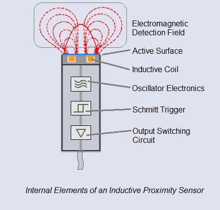
The oscillation produces an electromagnetic field in front of the sensor, because the coil is located right behind the “face” of the sensor. The technical name of the sensor face is “active surface”.
When a piece of conductive metal enters the zone defined by the boundaries of the electromagnetic field, some of the energy of oscillation is transferred into the metal of the target. This transferred energy appears as tiny circulating electrical currents called eddy currents. This is why inductive proxes are sometimes called eddy current sensors.
The flowing eddy currents encounter electrical resistance as they try to circulate. This creates a small amount of power loss in the form of heat (just like a little electric heater). The power loss is not entirely replaced by the sensor’s internal energy source, so the amplitude (the level or intensity) of the sensor’s oscillation decreases. Eventually, the oscillation diminishes to the point that another internal circuit called a Schmitt Trigger detects that the level has fallen below a pre-determined threshold. 
The short animation to the right shows the effect of a metal target on the sensor’s oscillating magnetic field. When you see the cable coming out of the sensor turn red, it means that metal was detected and the sensor has been switched on. When the target goes away, you can see that the oscillation returns to its maximum level and the sensor’s output is switched back off.
Want to learn more about the basic operating principles of Inductive Proximity Sensors? Here’s a short YouTube video covering the basics:


