Choosing the Right Sensor for Measuring Distance

Distance-measuring devices help with positioning, material flow control, and level detection. However, there are several options to consider when it comes to choosing the correct sensor technology to measure distance. Here I’ll cover the three most commonly used types in the industrial automation world today, including photoelectric, ultrasonic, and inductive.

Photoelectric sensors

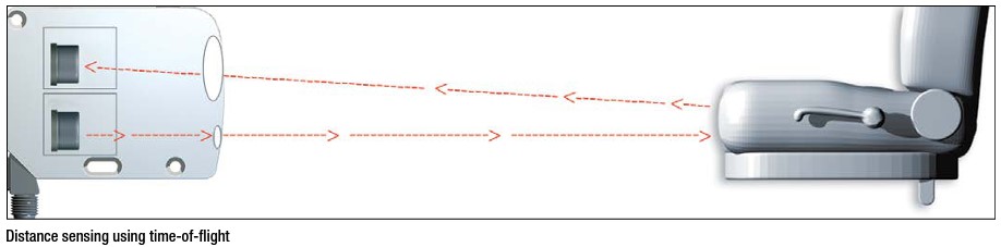
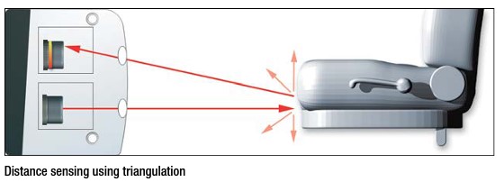
Photoelectric sensors use a light source, such as a laser or light-emitting diode, to reflect the light off an object’s surface to calculate the distance between the face of the sensor and the object itself. The two basic principles for how the sensor calculates the distances are the time of flight (TOF) and triangulation.

    • Time of flight photoelectric distance measurement sensors derive the distance measurement based on the time it takes the light to travel from the sensor to the object and return. These sensors are used to measure over long distances, generally in the range between 500 millimeters and up to 5 meters, with a resolution between 1 to 5 millimeters, depending on the sensor specifications. Keep in mind that this sensor technology is also used in range-finding equipment with a much greater sensing range than traditional industrial automation sensors.

    • In the triangulation measurement sensor, the sensor housing, light source, and light reflection form a triangle. The distance measurement is based on the light reflection angle within its sensing range with high accuracy and resolution. These sensors have a much smaller distance measurement range that is limited to between 20 and 300 millimeters, depending on the sensor specifications.

The pros of using photoelectric distance measurement sensors are the range, accuracy, repeatability, options, and cost. The main con for using photoelectric sensors for distance measurement is that they are affected by dust and water, so it is not recommended to use them in a dirty environment. The object’s material, surface reflection, and color also affect its performance.

Photoelectric distance measurement sensors are used in part contouring, roll diameter measurement, the position of assemblies, thickness detection, and bin-level detection applications.

Ultrasonic sensors

Ultrasonic distance sensors work on a similar principle as photoelectric distance sensors but instead of emitting light, they emit sound waves that are too high for humans to hear, and they use the time of flight of reflecting sound wave to calculate the distance between the object and the sensor face. They are insensitive to the object’s material, color, and surface finish. They don’t require the object or target to be made of metal like inductive position sensors (see below). They can also detect transparent objects, such as clear bottles or different colored objects, that photoelectric sensors would have trouble with since not enough light would be reflected back to reliably determine the distance of an object. The ultrasonic sensors have a limited sensing range of approximately 8 meters.

A few things to keep in mind that negatively affect the ultrasonic sensor is when the object or target is made of sound-absorbing material, such as foam or fabric, where the object absorbs enough soundwave emitted from the sensor making the output unreliable. Also, the sensing field gets progressively larger the further away it gets from the sensing face, thus making the measurement inaccurate if there are multiple objects in the sensing field of the sensor or if the object has a contoured surface. However, there are sound-focusing attachments that are available to limit the sensing field at longer distances making the measurements more accurate.

Inductive sensors

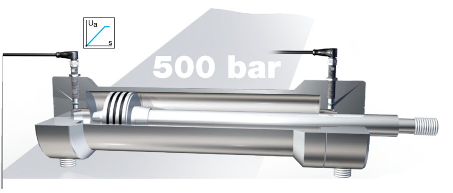
Inductive distance measurement sensors work on the same principle as inductive proximity sensors, where a metal object penetrating the electromagnetic field will change its characteristics based on the object size, material, and distance away from the sensing face. The change of the electromagnetic field detected by the sensor is converted into a proportional output signal or distance measurement. They have a quick response time, high repeatability, and linearity, and they operate well in harsh environments as they are not affected by dust or water. The downside to using inductive distance sensors is that the object or target must be made of metal. They also have a relatively short measurement range that is limited to approximately 50 millimeters.

Several variables exist to consider when choosing the correct sensor technology for your application solution, such as color, material, finish, size, measurement range, and environment. Any one of these can have a negative effect on the performance or success of your solution, so you must take all of them into account.

Inductive Sensors and Their Unlimited Uses in Automation

Inductive sensors (also known as proximity sensors or proxes) are the most commonly used sensors in mechanical engineering and industrial automation. When they were invented in the 1960s, they marked a milestone in the development of control systems. In a nutshell, they generate an electromagnetic field that reacts to metal targets that approach the sensor head. They even work in harsh environments and can solve versatile applications.

There are hardly any industrial machines that work without inductive sensors. So, what can be solved with one, two, three, or more of them?

What can you do with one inductive sensor?

Inductive sensors are often used to detect an end position. This could be in a machine for end-of-travel detection, but also in a hydraulic cylinder or a linear direct drive as an end-of-stroke sensor. In machine control, they detect many positions and trigger other events. Another application is speed monitoring with a tooth wheel.

What can you do with two inductive sensors?

By just adding one more sensor you can get the direction of rotational motion and take the place of a more expensive encoder. In a case where you have a start and end position, this can also be solved with a second inductive sensor.

What can you do with three inductive sensors?

In case of the tooth wheel application, the third sensor can provide a reference signal and the solution turns into a multiturn rotary encoder.

What can I do with four inductive sensors and more?

For multi-point positioning, it may make sense to switch to a measurement solution, which can also be inductive. Beyond that, an array of inductive sensors can solve identification applications: In an array of 2 by 2 sensors, there are already 16 different unique combinations of holes in a hole plate. In an array of 3 by 3, it would be 512 combinations.

Factor 1 sensors make auto production more flexible

Have you ever climbed a mountain with a backpack? Then you understand that the lower the load, the less power is needed and the lower the energy consumption. The same is true for cars. And in regard to electric vehicles, this is even more important: The more weight that can be saved somewhere else, the larger the battery can be, thus increasing the range of the electric car.

Lightweight construction is key for weight reduction. By using a sensible mix of materials, weight can be saved without compromising functionality and safety or drastically increasing costs. High-strength steels or light metals are used for body parts or seat frames. However, this mix of materials has an impact on automotive production when it comes to selecting the sensor technology. Inductive sensors have become an indispensable part of automotive construction; however, they react to different metals. This would mean frequent adjustments during production. Fortunately, we have Factor 1 sensors.

Inductive sensors react to metals. Their task is to detect metal objects without contact. The distance at which the corresponding object can be detected by the respective sensor is called the switching distance. The switching distance for standard inductive sensors depends on the material of the metal. Steel, for example, is detected much better than aluminum or copper. The switching distance can be reduced by up to 70% for non-ferromagnetic materials.


To eliminate this problem, Factor 1 sensors were developed. They offer all of the advantages of inductive sensors with the added bonus of having the same switching distance for all metals. This makes them ideally suited for the detection of changing objects (steel, aluminum, brass, copper etc.) and a perfect fit for the production of electric cars or anywhere different types of metals need to be used and identified. And because Factor 1 sensors are magnetic-field resistant, they can be used in areas  with strong electromagnetic fields, such as welding plants.

For more information, visit https://www.balluff.com/local/us/products/product-overview/sensors/inductive-sensors/#/inductive-factor-1-sensors

Back to the Basics: Object Detection

In the last post about the Basics of Automation, we discussed how humans act as a paradigm for automation. Now, let’s take a closer look at how objects can be detected, collected and positioned with the help of sensors.

Sensors can detect various materials such as metals, non-metals, solids and liquids, all completely without contact. You can use magnetic fields, light and sound to do this. The type of material you are trying to detect will determine the type of sensor technology that you will use.

Object Detection 1

Types of Sensors

  • Inductive sensors for detecting any metallic object at close range
  • Capacitive sensors for detecting the presence of level of almost any material and liquid at close range
  • Photoelectric sensors such as diffuse, retro-reflective or through-beam detect virtually any object over greater distances
  • Ultrasonic sensors for detecting virtually any object over greater distances

Different Sensors for Different Applications

The different types of sensors used will depend on the type of application. For example, you will use different sensors for metal detection, non-metal detection, magnet detection, and level detection.

Detecting Metals

If a workpiece or similar metallic objects Object Detection 2should be detected, then an inductive sensor is the best solution. Inductive sensors easily detect workpiece carriers at close range. If a workpiece is missing it will be reliably detected. Photoelectric sensors detect small objects, for example, steel springs as they are brought in for processing. Thus ensures a correct installation and assists in process continuity. These sensors also stand out with their long ranges.

Detecting Non-Metals

If you are trying to detect non-metal objects, for example, the height of paper stacks, Object Detection 3then capacitive sensors are the right choice. They will ensure that the printing process runs smoothly and they prevent transport backups. If you are checking the presence of photovoltaic cells or similar objects as they are brought in for processing, then photoelectic sensors would be the correct choice for the application.

Detecting Magnets

Object Detection 4

To make sure that blister packs are exactly positioned in boxes or that improperly packaged matches are sorted out, a magnetic field sensor is needed which is integrated into the slot. It detects the opening condition of a gripper, or the position of a pneumatic ejector.


Level Detection

What if you need to detect the level of granulate in containers? Then the solution is to use capacitive sensors. To accomplish this, two sensors are attached in the containers, offset from each other. A signal is generated when the minimum or maximum level is exceeded. This prevents over-filling or the level falling below a set amount. However, if you would like to detect the precise fill height of a tank without contact, then the solution would be to use an ultrasonic sensor.

Stay tuned for future posts that will cover the essentials of automation. To learn more about the Basics of Automation in the meantime, visit www.balluff.com.

Solar tracking systems and sensors

Over the last few years there has been a lot of discussion on how we will meet the global energy demand in the future. And what will be the technologies to generate it? In the end it all comes down to the levelized cost of electricity (LCOE), which is the sum of all costs of a power plant divided by the total electricity that is generated over the plant’s lifetime. All companies in the renewable energy industry focus on reaching lower LCOE compared to conventional power generation (especially gas). Their biggest advantage is that there are no costs for fuel (sun light, wind, water).

solarpanelsLet’s take solar power as an example. Principally there are two ways to use the sun light: First it can be converted directly to electricity (photovoltaics). Second, it can be used indirectly by generating thermal energy (concentrated solar power). In order to reach higher efficiency solar trackers are used to orient photovoltaic panels, reflectors, or mirror towards the sun. On the other hand they add costs to the system. Therefore it must be carefully calculated whether a tracker (single or dual axis) is required or not (fixed installation).

solarpanels2Single axis trackers are used to position photovoltaic panels, parabolic troughs or linear Fresnel collectors from east to west on a north to south orientation. Depending on the required tracking accuracy different sensors are used for this task. As most of the photovoltaic trackers use electric linear actuators, very often inductive sensors are installed on the actuator for position feedback. They are cost optimized and are a standard feature in the actuators. Another option is to use inclination sensors that are directly mounted on the rotating shaft to provide angle feedback (e.g. in linear Fresnel plants). As inclinometers are mounted on the moving part, there is cable wear that could lead to failure over time. For high end tracking, as is required in parabolic trough plants, magnetic tape systems are used as rotary encoders. A magnetic tape is mounted around the shaft and a sensor head is installed on the frame of the tracker. The sensor counts the pulses accurately and provides continuous position feedback without any wear.

solarpanels3Dual axis trackers are used to position concentrated photovoltaic (CPV) panels, parabolic reflectors (dish) or mirrors (heliostats). Especially in central receiver plants high accuracy is required. They need high temperatures and therefore have to focus lots of light on a central receiver on top of a tower in the middle of the heliostat field. As there is an azimuth and an elevation axis, two position feedback systems are required. The elevation angle could be solved with an inclinometer, but this does not work for the azimuth position.  Again, the position could be measured with embedded rotary encoders directly on the drive. But there is again backlash, and accuracy is of highest importance as heliostats could be one mile away from the central receiver. Magnetically coded position and angle measurement systems can be mounted on both axis (azimuth and elevation) and provide direct position feedback with highest accuracy.

More information can be found in this brochure about power generation. http://asset.balluff.com/std.lang.all/pdf/binary/861522_162563_1305_en-US.pdf

Special thank you to Bernd Schneider, Industry Manger – Balluff GmbH for contributing to this post.

Inductive Sensors for Washdown Conditions

WashdownSensorsWhen selecting the proper Inductive sensor it is very important to understand the type of application environment the sensor will be installed in. In previous posts, I have blogged about various types of sensors and how they fit into the application mix. For example, a welding application will need specific sensor features that will help combat the normal hostilities that are common to heat, weld spatter and impact due to tight tolerances within the fixture areas.

Inductive sensors are also used more and more in aggressive environments including machine tools, stamp and die, and food and beverage applications. Many times within these types of applications there are aggressive chemicals and cleaners that are part of the application process or simply part of the cleanup procedure that also
mandates high pressure wash down procedures.

So, when we have a stamping or food and beverage application that uses special oils or coolants we know a standard sensor is on borrowed time. This is where harsh environment sensors come in as they offer higher IP ratings with no LED function indicators that seals the sensor to withstand the harshest processes. They also will have high grade stainless steel housings special plated electronics along with additional O-rings making them ideal for the most hostile environment.

InductiveWashdownFeatures:

  • High grade stainless steel housing
  • No LED indicator
  • Gold plated internal contacts
  • Additional sealing O-rings
  • Increased IP ratings
  • Higher temperature ratings

For more information on inductive sensors for harsh environments you can visit the Balluff website at www.balluff.us.

High Pressure Inductive Sensors with Analog Feedback

In my previous blog post we covered the Anatomy of a High Pressure Proximity Sensor. That post covered the different mechanical housing designs and special properties that go into high pressure sensor products with discrete outputs. That is great information to know when specifying the correct sensor for a particular application. In today’s competitive market and constant goals to improve processes, sensor’s that offer continuous feedback are required.

Hydraulic systems regulate speed of an actuator by regulating flow rate. The flow rate determines the speed of the cylinder spud that actuates inside the system. For example, an analog sensor can provide measurement to the controls with indication of slowing down or speeding up the actuator based on the analog feedback from the sensor in regard to position of the tapered section of the actuator. So, if the internal target gets larger with more position movement (stroke) the distant measurement changes and indicates that the end of stroke is near causing the controller to initiate a soft stop. This provides better control of the system offering a more efficient reliable process.

500barAnalog Inductive sensors provide an absolute voltage or current signal change proportional to the distance of a ferrous target. In high pressure applications that require more position feedback, an analog distance sensor can offer a solution as they also offer high – strength stainless steel housings with special sealing designs that allow pressure up to 500 bar and 85°C temperature ratings making them an ideal solution for valve speed control and soft starts with a non – contact design.

More information on high pressure analog inductive sensors is available on the Balluff website at www.balluff.us.

Let’s Get Small: The Drive Toward Miniaturization

minisensorGoing about our hectic daily lives, we tend to just take the modern cycle of innovation for granted. But when we stop to think about it, the changes we have seen in the products we buy are astonishing. This is especially true with regard to electronics. Not only are today’s products more feature-laden, more reliable, and more functional…they are also unbelievably small.

I remember our family’s first “cell phone” back in the ’90s. It was bolted to the floor of the car, required a rooftop antenna, and was connected to the car’s electrical system for power. All it did was place and receive phone calls. Today we are all carrying around miniature pocket computers we call “smartphones,” where the telephone functionality is – in reality – just another “app”.

Again going back two decades, we had a 32″ CRT analog television that displayed standard definition and weighed over 200 pounds; it took two strong people to move it around the house. Today it’s common to find 55″ LCD high-definition digital televisions that weigh only 50 pounds and can be moved around by one person with relative ease.

LabPhotoThese are just a couple of examples from the consumer world. Similar changes are taking place in the industrial and commercial world. Motors, controllers, actuators, and drives are shrinking. Today’s industrial actuators and motion systems offer either the same speed and power with less size and weight, or are simply more compact and efficient than ever before possible.

The advent of all this product miniaturization is driving a need for equally miniaturized manufacturing and assembly processes. And that means rising demand for miniaturized industrial sensors such as inductive proximity sensors, photoelectric presence sensors, and capacitive proximity sensors.

Another thing about assembling small things: the manufacturing tolerances also get small. The demand for sensor precision increases in direct proportion to manufacturing size reduction. Fortunately, miniature sensors are also inherently precision sensors. As sensors shrink in size, their sensing behavior typically becomes more precise. In absolute terms, things like repeatability, temperature drift, and hysteresis all improve markedly as sensor size diminishes. Miniature sensors can deliver the precise, repeatable, and consistent sensing performance demanded by the field of micro-manufacturing.

For your next compact assembly project, be sure to think about the challenges of your precision sensing applications, and how you plan to deploy miniature sensors to achieve consistent and reliable operation from your process.

For more information on precision sensing visit balluff.us/minis.

Anatomy of a High Pressure Inductive Proximity Sensor

Some industrial applications will require a sensor with special properties. This type of sensor offering is needed especially when pressure comes to play. In a wide range of hydraulic cylinder and valve applications high pressure sensors are exposed to hostile environments and are subject to pressure that a standard sensor simply cannot hold up in. For example 350 bar of pressure can be detrimental to a standard sensor as it is not designed for a pressure application.

High pressure inductive sensors are designed to withstand the severe duty of a high pressure application with product features like corrosion – resistant housing materials, high strength ceramic sensing faces and special sealing techniques such as undercut housings with sealing and support rings. This is very important because not only do we need to have a sensor that can withstand pressure on the face of the sensor without damage we also need to make sure we can keep the hydraulic fluid inside the cylinder or valve where it belongs.

In the photo below you will notice the undercut area at the sensing face of the sensor along with an O-ring and supporting backing ring to make sure the application is sealed tight.

installation instruction Installation Photo

There are several common sizes for different types of cylinder and valves however the same principle applies. Below is an example of a flange mount style offering. This type of sensor takes a different design approach that is bolted to the top side of a cylinder with a sealing O-ring under the mounting point.

Strokemaster Diagram

strokemaster photo

It’s also important to know what form factor is needed when specifying a high pressure inductive sensor. Typically you will see pressure options from 50 up to 500 bar. The dimensions of the cylinder or valve will determine what type of high pressure sensor is needed.

HighPressureGroup

To learn more visit www.balluff.us.

Back to the Basics: How Do I Wire a DC 2-wire Sensor?

In one of my previous post we covered “How do I wire my 3-wire sensors“. This topic has had a lot of interest so I thought to myself, this would be a great opportunity to add to that subject and talk about DC 2-wire sensors. Typically in factory automation applications 2 or 3 wire sensors are implemented within the process, and as you know from my prior post a 3 wire sensor has the following 3 wires; a power wire, a ground wire and a switch wire.

A 2-wire sensor of course only has 2 wires including a power wire and ground wire with connection options of Polarized and Non-Polarized. A Polarized option requires the power wire to be connected to the positive (+) side and the ground wire to be connected to the negative side (-) of the power supply. The Non-Polarized versions can be wired just as a Polarized sensor however they also have the ability to be wired with the ground wire (-) to the positive side and the power wire (+) to the negative side of the power supply making this a more versatile option as the sensor can be wired with the wires in a non – specific location within the power supply and controls.

In the wiring diagrams below you will notice the different call outs for the Polarized vs. Non-Polarized offerings.

PolarizedDiagramsnon-polarized diagramsNote: (-) Indication of Non-Polarized wiring.

While 3-wire sensors are a more common option as they offer very low leakage current, 2 wire offerings do have their advantages per application. They can be wired in a sinking (NPN) or sourcing (PNP) configuration depending on the selected load location. Also keep in mind they only have 2 wires simplifying connection processes.

For more information on DC 2- Wire sensors click here.