Flush, Non-Flush, or Quasi-Flush: Choosing the Right Proximity Sensor for Optimal Object Detection

Proximity sensors are aptly named for their ability to detect objects in close proximity. They are not suitable for detecting objects across a room or on a conveyor belt. Their focus is on detecting objects up close and personal. Inductive proximity technology allows detection from physical contact with the sensor head to a few millimeters away. When choosing the right type of inductive proximity technology, several factors must be considered. Let’s start at the beginning.

Inductive proximity sensors may seem magical, but they operate based on specific magical characteristics. To prove my point, show them (and try to explain them) to a kid. Imagine an invisible electromagnetic field surrounding the sensors. This field can only be disrupted by a metal target. Different metals can affect this field at varying distances, depending on the type of metal and the sensor used. In simple terms, the sensor can detect if an object is a metal and, to some extent, the type of metal– all without touching the object physically.

Now that we’ve covered the basics, let’s focus on understanding the characteristics of the magical electromagnet field, its impact on sensing range, mounting, and the risks of sensor and/or part damage.

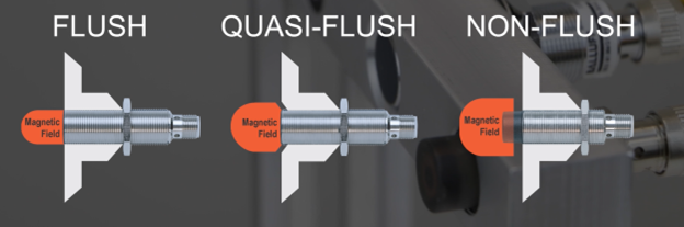
You may have heard the terms flush or non-flush used for inductive proximity sensors. I’ll throw one more into the mix: quasi-flush.

Non-flush mounting

Non-flush mount proximity sensors offer the longest range – the air gap between the target and the sensing head. This can be a good thing or a bad thing, depending on the situation. For precise positioning requirements, the extra range might cause issues. However, if precision is unnecessary, the extended ranges could be beneficial as objects might come into range slightly differently. One major downside of non-flush sensors is their susceptibility to damage. Typically, several millimeters to half an inch of the sensing head is exposed, increasing the risk of shearing off the sensor head or damaging the object you are detecting.

Flush mount proximity

With flush-mount proximity, you gain some protection for both the sensor head and the object being detected, but it comes with a trade-off of reduced sensing range. This is because the shape of the electromagnetic field coming out of the sensing head is focused to avoid triggering the mounting block or other hardware.

Quasi-flush mounting

If you are looking for a Goldilocks solution, consider quasi-flush mounting. With this style of sensing head, you recess the sensor into a mounting block, which helps focus the electromagnet field a bit more, thereby adding more field length compared to a flush mount. It is important to ensure your mounting block has a bevel around the sensing head to avoid false triggers of the output.

So, when deciding which type to use, I recommend using flush or quasi-flush sensors for any target that may come into contact with the sensing head. This choice will prolong the sensor’s life and better ensure proper target triggering. Non-flush sensors are great when you need a larger gap between the target and the sensing head, and precision is not a big issue.

In closing, proximity sensing is designed to be a non-contact form of object detection, specifically metal objects. The goal is to avoid any contact with the sensing head, although we’re aware that object/sensor collisions can happen.

Boosting Sensor Resilience in Welding With Self-Bunkering Inductive Proximity Sensors

A welding cell will press the limits of any sensor placed in its proximity. Avoiding weld spatter, magnetic fields, extreme temperatures, and impact damage are common challenges in a harsh welding environment. And when sensors fail in these conditions, it can significantly disrupt production uptime. To prevent such disruptions, manufacturers explore more robust sensor mounting solutions, such as proximity mounts, bunker blocks, and other protective devices to shield sensors from these harsh conditions. The self-bunkering inductive proximity sensor plays a key role in alleviating the issues, especially in situations where other accessories are not an option due to limited space.

Weld spatter and magnetic field resistant

In many welding applications, the substantial currents involved can generate heightened magnetic fields, making a welding cell vulnerable to interference. This interference can lead a basic proximity sensor to trigger, even though a part may not be present. The self-bunkering proximity sensor is designed to resist magnetic fields, allowing it to work much closer to the welding surface than a typical inductive sensor. Additionally, the sensor comes with a polytetrafluoroethylene (PTFE) weld coating, allowing for easy removal of the spatter buildup with abrasive tools like a wire brush.

Guard against heavy impacts

Again, the self-bunkering inductive proximity sensor is built for rugged environments. It features a thick, strong one-piece connector body and super thick brass housing to buffer the internal electronics from external impacts and conductive heat. It also includes a deflection ring and a non-brittle, ferrite-free coil carrier to protect the sensor face from direct impacts, disperse shock, and safeguard internal sensing components. The wide-radius corners offer stress relief at the major junction points of the connector body and housing.

Withstand extreme temperatures

With a ceramic PTFE-coated face plate, the sensor can resist up to 2200°F weld spatter burn through from the front. The rest of the body, coated with PTFE and paired with an extra-thick brass housing, provides protection for the sensor up to 300°F. This means that if the sensor is properly maintained, its lifetime should be quite a bit longer than a standard inductive sensor.

Don’t replace, defend

The core components of the proximity sensor can be destroyed if any of the three critical failures – conducted heat, impact, or spatter – occur in combination. To prevent this, the product incorporates a collection of design measures intended to create a virtually impenetrable shield around the internal critical components.

In summary, the self-bunkering inductive proximity sensor is a key solution to combat the challenges sensors face in harsh welding environments that will ultimately disrupt production. Its resistance to magnetic fields and ability to withstand heavy impacts and extreme temperatures, especially in situations with limited space, ensures the protection of the critical sensor components and extended sensor lifespan.

Capacitive, the Other Proximity Sensor

What is the first thing that comes to mind if someone says “proximity sensor?” My guess is the inductive sensor, and justly so because it is the most used sensor in automation today. There are other technologies that use the term proximity in describing the sensing mode, including diffuse or proximity photoelectric sensors that use the reflectivity of the object to change states and proximity mode of ultrasonic sensors that use high-frequency sound waves to detect objects. All these sensors detect objects that are in close proximity to the sensor without making physical contact. One of the most overlooked or forgotten proximity sensors on the market today is the capacitive sensor.

Capacitive sensors are suitable for solving numerous applications. These sensors can be used to detect objects, such as glass, wood, paper, plastic, or ceramic, regardless of material color, texture, or finish. The list goes on and on. Since capacitive sensors can detect virtually anything, they can detect levels of liquids including water, oil, glue, and so forth, and they can detect levels of solids like plastic granules, soap powder, sand, and just about anything else. Levels can be detected either directly, when the sensor touches the medium, or indirectly when it senses the medium through a non-metallic container wall.

Capacitive sensors overview

Like any other sensor, there are certain considerations to account for when applying capacitive, multipurpose sensors, including:

1 – Target

    • Capacitive sensors can detect virtually any material.
    • The target material’s dielectric constant determines the reduction factor of the sensor. Metal / Water > Wood > Plastic > Paper.
    • The target size must be equal to or larger than the sensor face.

2 – Sensing distance

    • The rated sensing distance, or what you see in a catalog, is based on a mild steel target that is the same size as the sensor face.
    • The effective sensing distance considers mounting, supply voltage, and temperature. It is adjusted by the integral potentiometer or other means.
    • Additional influences that affect the sensing distance are the sensor housing shape, sensor face size, and the mounting style of the sensor (flush, non-flush).

3 – Environment

    • Temperatures from 160 to 180°F require special considerations. The high-temperature version sensors should be used in applications above this value.
    • Wet or very humid applications can cause false positives if the dielectric strength of the target is low.
    • In most instances, dust or material buildup can be tuned out if the target dielectric is higher than the dust contamination.

4 – Mounting

    • Installing capacitive sensors is very similar to installing inductive sensors. Flush sensors can be installed flush to the surrounding material. The distance between the sensors is two times the diameter of the sensing distance.
    • Non-flush sensors must have a free area around the sensor at least one diameter of the sensor or the sensing distance.

5 – Connector

    • Quick disconnect – M8 or M12.
    • Potted cable.

6 – Sensor

    • The sensor sensing area or face must be smaller or equal to the target material.
    • Maximum sensing distance is measured on metal – reduction factor will influence all sensing distances.
    • Use flush versions to reduce the effects of the surrounding material. Some plastic sensors will have a reduced sensing range when embedded in metal. Use a flush stainless-steel body to get the full sensing range.

These are just a few things to keep in mind when applying capacitive sensors. There is not “a” capacitive sensor application – but there are many which can be solved cost-effectively and reliably with these sensors.

Avoid Downtime in Metal Forming With Inductive & Photoelectric Sensors

Industrial sensor technology revolutionized how part placement and object detection are performed in metal forming applications. Inductive proximity sensors came into standard use in the industry in the 1960s as the first non-contact sensor that could detect ferrous and nonferrous metals. Photoelectric sensors detect objects at greater distances. Used together in a stamping environment, these sensors can decrease the possibility of missing material or incorrect placement that can result in a die crash and expensive downtime.

Inductive sensors

In an industrial die press, inductive sensors are placed on the bottom and top of the dies to detect the sheet metal for stamping. The small sensing range of inductive sensors allows operators to confirm that the sheet metal is correctly in place and aligned to ensure that the stamping process creates as little scrap as possible.

In addition, installing barrel-style proximity sensors so that their sensing face is flush with the die structure will confirm the creation of the proper shape. The sensors in place at the correct angles within the die will trigger when the die presses the sheet metal into place. The information these sensors gather within the press effectively make the process visible to operators. Inductive sensors can also detect the direction of scrap material as it is being removed and the movement of finished products.

Photoelectric sensors

Photoelectric sensors in metal forming have two main functions. The first function is part presence, such as confirming that only a single sheet of metal loads into the die, also known as double-blank detection. Doing this requires placing a distance-sensing photoelectric sensor at the entry-way to the die. By measuring the distance to the sheet metal, the sensor can detect the accidental entry of two or more sheets in the press. Running the press with multiple metal sheets can damage the die form and the sensors installed in the die, resulting in expensive downtime while repairing or replacing the damaged parts.

The second typical function of photoelectric sensors verifies the movement of the part out of the press. A photoelectric light grid in place just outside the exit of the press can confirm the movement of material out before the next sheet enters into the press. Additionally, an optical window in place where parts move out will count the parts as they drop into a dunnage bin. These automated verification steps help ensure that stamping processes can move at high speeds with high accuracy.

These examples offer a brief overview of the sensors you mostly commonly find in use in a die press. The exact sensors are specific to the presses and the processes in use by different manufacturers, and the technology the stamping industry uses is constantly changing as it advances. So, as with all industrial automation, selecting the most suitable sensor comes down to the requirements of the individual application.

Mobile Equipment Manufacturers: Is It Time to Make the Switch to Inductive Position Sensors?

Manufacturers of mobile equipment are tasked with the never-ending pursuit of making their machines more productive while adhering to the latest safety regulations, and all at less cost. To help achieve these goals, machines today use electronic control modules to process inputs and provide outputs that ultimately control the machine functions. Yet with all the changes in recent years, one component left over from that earlier era remains in regular use — the mechanical switch.  Switches offered a variety of levers, rollers, and wands for actuation, and many were sealed for an IP67 rating for outdoor use, but they came with an array of problems, including damaged levers, contact corrosion, arcing concerns, dirt or grain dust ingress, and other environmental hazards. Still, overall they were an acceptable and inexpensive way to receive position feedback for on/off functions.

Today, mechanical switches can still be found on machines used for boom presence, turret location, and other discrete functions. But are they the right product for today’s machines?

The original design parameters may have required the switch to drive the load directly, and therefore a rating of 10A@240V might be a good design choice for the relay/diode logic circuits of the past. But a newly designed machine may be switching mere milliamps through the switch into the control module. Does the legacy switch have the proper contact plating material for the load today? Switches use rare metals such as rhodium, palladium, platinum, gold, and silver in attempts to keep the contact resistance low and to protect those contacts from corrosion. Consequently, as China pursues Nonroad Stage IV standards, these metals, some also used in catalytic converters, have sharply increased in price, leading to substantial cost increases to switch manufacturers and ultimately switch users.

A better approach to position feedback for today’s mobile machines is the inductive position sensor. Inductive sensors offer a sealed, non-contact alternative to mechanical switches. Sensing ferrous and non-ferrous metals without physical contact, they eliminate many of the field problems of the past, and non-metallic substances such as water, dirt, and grain dust, do not affect the operation. These qualities make the sensor very suitable for the harsh conditions found in agricultural and construction environments.

Inductive proximity sensors come in a variety of form factors:

Threaded cylindrical – With zinc-plated brass or stainless-steel housings, the threaded barrel styles are popular for their ease of mounting and gap adjustment.  

1

Low profile rectangular – These “flatpack” style sensors are great under seats for operator presence.

2

Block designs – The compact, cubed package is ideal for larger sensing ranges.

3

Large cylindrical – These large “pancake” style sensors are great for detecting suspension movements and other applications requiring extreme ranges.

4

Inductive position sensors are more than just a discrete product used for detecting linkage, operator presence, or turret stops; They can also perform the duties of a speed sensor by counting teeth (or holes) to determine the RPM of a rotating shaft. Other models offer analog outputs to provide a continuous feedback signal based on the linear location of a metal linkage or lever. Safety rated outputs, high temperatures, and hazardous area options are some of the many product variants available with this electromagnetic technology.
So, perhaps it’s time to review that legacy switch and consider an inductive sensor?
To learn how an inductive position sensor performs its magic, please take a look at an earlier blog:

Basic Operating Principle of an Inductive Proximity Sensor

Where Did You Find That Sensor?

I recently visited a customer that has a large amount of assembly lines where they have several machine builders manufacturing assembly process lines to their specification. This assembly plant has three different business units and unfortunately, they do not communicate very well with each other. Digging deeper into their error proofing solutions, we found an enormous amount of sensors and cables that could perform the same function, however they mandated different part numbers. This situation was making it very difficult for maintenance employees and machine operators to select the best sensor for the application at hand due to redundancy with their sensor inventory.

The customer had four different types of M08 Inductive Proximity sensors that all had the same operating specifications with different mechanical specifications. For example, one sensor had a 2mm shorter housing than one of the others in inventory. These 2mm would hardly have an effect when installed into an application 99% of the time. The customer also had other business units using NPN output polarity VS PNP polarity making it even more difficult to select the correct sensor and in some situations adding even more downtime when the employee tried to replace an NPN sensor where a PNP offering was needed. As we all know, the NPN sensor looks identical to the PNP offering just by looking at it. One would have to really understand the part number breakdown when selecting the sensor, and when a machine is down this sometimes can be overlooked. This is why it is so important to standardize on sensor selection when possible. This will result in more organized inventory by reducing part numbers, reducing efforts from purchasing and more importantly offering less confusion for the maintenance personel that keep production running.

Below are five examples of M08 Inductive sensors that all have the same operating specifications. You will notice the difference in housing lengths and connection types. You can see that there can be some confusion when selecting the best one for a broad range of application areas. For example, the housing lengths are just a few millimeters different. You can clearly see that one or two of these offerings could be installed into 99% of the application areas where M08 sensors are needed for machine or part position or simply error proofing a process.

Shawn1Shawn2.pngShawn3Shawn4                                                             Shawn5

For more information on standardizing your sensor selection visit www.balluff.com


Reliable Part Exit/Part-Out Detection

Walk into any die shop in the US and nine out of ten times, we discover diffuse reflective sensors being used to detect a large part or a small part exiting a die. Many people have success using this methodology, but lubrication-covered tumbling parts can create challenges for diffuse-reflective photoelectric sensing devices for many reasons:

  1. Tumbling parts with many “openings” on the part itself can cause a miss-detected component.
  2. Overly-reflective parts can false triggering of the output.
  3. Dark segments of the exiting part can cause light absorption. Remember, a diffuse sensors sensing distance is based on reflectivity. Black or dark targets tend to absorb light and not reflect light back to the receiver.
  4. Die lube/misting can often fog over a photoelectric lens requiring maintenance or machine down time.

The solution: Super Long Range Inductive Sensors placed under chutes

Most metal forming personnel are very familiar with smaller versions of inductive proximity sensors in tubular sizes ranging from 3mm through 30mm in diameter and with square or “block style” inductive types (flat packs, “pancake types”, etc.) but it is surprising how many people are just now discovering “Super Long Range Inductive Proximity” types. Super Long Range Inductive Proximity Sensors have been used in metal detection applications for many years including Body-In-White Automotive applications, various segments of steel processing and manufacturing, the canning industry, and conveyance.

Benefits of Using A UHMW Chute + Super Long Range Inductive Proximity Sensor in Part Exit/Part-Out Applications:

  1. It is stronger and quieter than parts flowing over a metal chute, readily available in standard and custom widths, lengths and thicknesses to fit the needs of large and small part stampers everywhere.
  2. UHMW is reported to be 3X stronger than carbon steel.
  3. UHMW is resistant to die lubes.
  4. UHMW allows Super Long Range Inductive Proximity Sensors to be placed underneath and to be “tuned” to fit the exact zone dimension required to detect any part exiting the die (fixed ranges and tunable with a potentiometer). The sensing device is also always out of harm’s way.
  5. Provides an option for part detection in exiting applications that eliminates potential problems experienced in certain metal forming applications where photoelectric sensing solutions aren’t performing optimally.
A Two-Out Die with Metallic Chute

Not every Part Exit/Part-Out application is the same and not every die, stamping application, vintage of equipment, budget for sensing programs are the same. But it’s important to remember in the world of stamping, to try as consistently as possible to think application specificity when using sensors.  That is, putting the right sensing system in the right place to get the job done and to have as many technical options available as possible to solve application needs in your own “real world” metal forming operation.  We believe the UHMW + Super Long Range Inductive System is such an option.

You can learn more in the video below or by visiting www.balluff.us.

Proximity Sensor Switching Distances

operating-distance
Diagram showing the relationship between the various operating distances of an inductive proximity sensor.

When looking at a data sheet for an inductive proximity sensor, there are usually several different specifications listed with regard to the switching distance (or operating distance). Which of these various specifications really matter to someone trying to use a prox sensor in a real-world application? How can a specifier or user decide which sensor is going to work best in their situation?

Fortunately, there is an international standard that defines sensor switching distances and spells out test methods to assure that sensor specifications from product to product and even manufacturer to manufacturer can be directly compared “apples to apples.”

This standard is IEC 60947-5-2 Low voltage switchgear and controlgear – Part 5-2: Control circuit devices and switching elements – Proximity switches.

Operating (switching) distance s

In the diagram shown here, the letter “s” refers to a given sensor specimen’s actual switching distance when tested.  It is defined as the distance (between the standard target and the sensing face of the proximity switch) at which a signal change is generated. For a normally open sensor, the target approaches the sensor axially, that is, the sensor approaches the active surface from the front (not the side). There are several subscripts used to describe different aspects of a sensor’s switching behavior.

Rated operating distance sn

… is the nominal switching distance of the sensor. It is simply used as a standard reference value. The rated operating distance is the best figure to use when comparing different sensor models to get an idea of their essential sensing distance capabilities.

Effective operating distance sr

…is the range of actual switching distances that any given proximity sensor will fall into when measured under specified conditions of mounting, temperature, and supply voltage. For well-designed and manufactured sensors, the sensor will be triggered between 90% and 110% of the rated operating distance. For example, various samples of a proximity sensor model with a rated operating distance (sn) of 8mm may deliver switch-on points anywhere between 7.2mm and 8.8mm.

Usable operating distance su

…takes into account the effects of the sensor’s full ambient temperature range (low to high) and variation of the supply voltage from 85% to 110% of the nominal voltage rating. The IEC standard requires the usable operating distance (su) to be between 90% and 110% of the effective operating distance (sr). For our example of a sensor with a rated operating distance (sn) of 8mm, the usable operating distance would fall between 6.5mm and 8.8mm. Pop quiz: why is the max of usable operating distance not 9.7mm (sr of 8.8mm * 110%)? Answer: the usable operating distance can always be less than but can never be greater than the maximum effective operating distance.

Assured operating distance sa

This is the distance of the target to the sensor where the sensor can be guaranteed to have turned on. If a target approaches within the assured operating distance, you can be confident that the sensor will detect it.  It is 90% of sr which is in turn 90% of sn, which is in effect 81% of sn. Going back to our example of a sensor with a rated operating distance (sn) of 8mm, sa would be 81% * 8mm = 6.5mm. So in essence, sa = su(min).

Differential travel H

Now when the target recedes, at what distance will the sensor switch off? All good-quality sensors have a built-in property called hysteresis, which means that the sensor will turn off when the target is further away from the sensor than the point where it turns on. This is necessary to prevent chattering and instability when the target approaches the sensor. We want the sensor to turn on and stay on, even if the target might be vibrating as it crosses the threshold of detection. For most sensors, it is defined as ≤ 20% of the effective operating distance sr. The differential travel is added to the value of sr to define the switch-off point.

In practice, for any group of sensors, the minimum value of H would be zero and the maximum value would be sr(max) + 20% of sr(max). For our example of a sensor with a rated operating distance (sn) of 8mm, 7.2mm ≤  sr  ≤ 8.8mm. So, the range of switch-off points would be 7.2mm ≤  sr+H  ≤ 10.6mm. It might sound like a large range, but for any given sensor specimen the switch-off point is never greater than 20% of that particular sensor’s switch-on point.

Conclusion

The good news is that you don’t have to conduct sensor tests yourself or go through all of these calculations manually to determine a sensor’s performance envelope. The sensor manufacturer provides all of these useful figures pre-calculated for you in the sensor data sheet.

Learn more about the basics of the most popular automation sensor here.

Reed Switches vs. Magnetoresistive Sensors (GMR)

In a previous post we took a look at magnetic field sensors vs inductive proximity sensors for robot grippers. In this post I am going to dive a little deeper into magnetic field sensors and compare two technologies: reed switches, and magnetoresistive sensors (GMR).

Reed Switches

PrintThe simplest magnetic field sensor is the reed switch. This device consists of two flattened ferromagnetic nickel and iron reed elements, enclosed in a hermetically sealed glass tube. As an axially aligned magnet approaches, the reed elements attract the magnetic flux lines and draw together by magnetic force, thus completing an electrical circuit.

While there are a few advantages of this technology like low cost and high noise immunity, those can be outweighed by the numerous disadvantages. These switches can be slow, are prone to failure, and are sensitive to vibration. Additionally, they react only to axially magnetized magnets and require high magnet strength.

Magnetoresistive Sensors (GMR)

PrintThe latest magnetic field sensing technology is called giant magnetoresistive (GMR). Compared to Reed Switches GMR sensors have a more robust reaction to the presence of a magnetic field due to their high sensitivity, less physical chip material is required to construct a practical GMR magnetic field sensor, so GMR sensors can be packaged in much smaller housings for applications such as short stroke cylinders.

GMR sensors have quite a few advantages over reed switches. GMR sensors react to both axially and radially magnetized magnets and also require low magnetic strength. Along with their smaller physical size, these sensors also have superior noise immunity, are vibration resistant. GMR sensors also offer protection against overload, reverse polarity, and short circuiting.

Basic Sensors for Robot Grippers

Robot gripper with inductive proximity sensors mounted

Typically when we talk about end-of-arm tooling we are discussing how to make robot grippers smarter and more efficient. We addressed this topic in a previous blog post, 5 Tips on Making End-of-Arm Tooling Smarter. In this post, though, we are going to get back to the basics and talk about two options for robot grippers: magnetic field sensors, and inductive proximity sensors.

One of the basic differences is that detection method that each solution utilizes. Magnetic field sensors use an indirect method by monitoring the mechanism that moves the jaws, not the jaws themselves. Magnetic field sensors sense magnets internally mounted on the gripper mechanism to indicate the open or closed position. On the other hand, inductive proximity sensors use a direct method that monitors the jaws by detecting targets placed directly in the jaws. Proximity sensors sense tabs on moving the gripper jaw mechanism to indicate a fully open or closed position.

BMF_Grippers
Robot gripper with magnetic field sensors mounted

Additionally, each solution offers its own advantages and disadvantages. Magnetic field sensors, for example, install directly into extruded slots on the outside of the cylinder, can detect an extremely short piston stroke, and offer wear-free position detection. On the other side of the coin, the disadvantages of magnetic field sensors for this application are the necessity of a magnet to be installed in the piston which also requires that the cylinder walls not be magnetic. Inductive proximity sensors allow the cylinder to be made of any material and do not require magnets to be installed. However, proximity sensors do require more installation space, longer setup time, and have other variables to consider.