Understanding Discrete and Analog Sensors: Maximizing Efficiency and Reliability in Industrial Automation

In industrial automation, the choice between discrete and analog sensors plays a pivotal role in determining the efficiency, accuracy, and reliability of systems across various industries. Both sensor types offer distinct advantages and applications tailored to specific industrial needs. In this post, I examine the differences between discrete and analog sensors, highlighting their applications and when to choose each in industries ranging from manufacturing to energy production.

Understanding discrete sensors

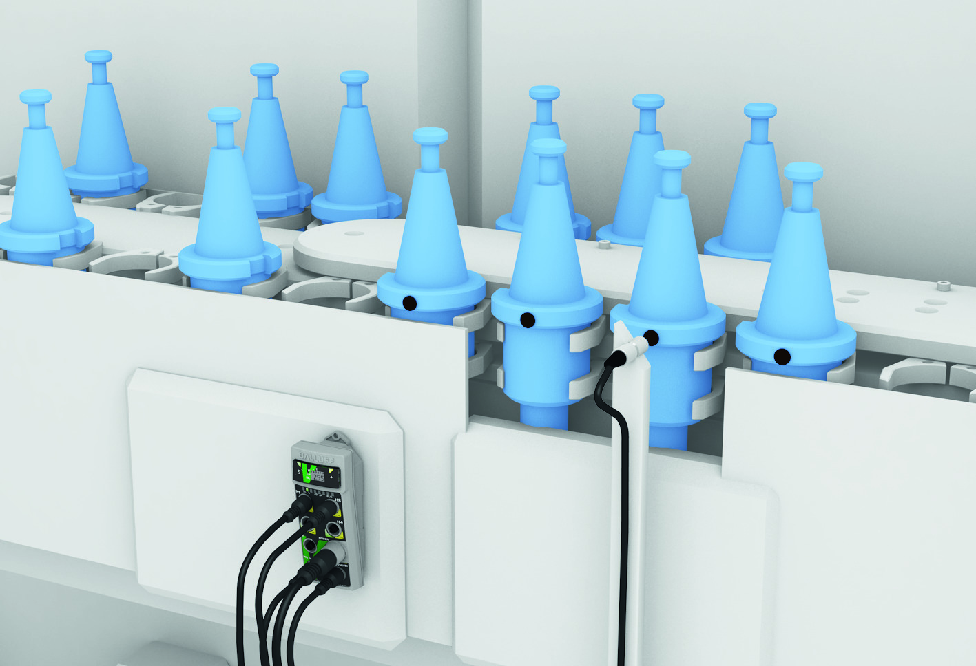
Discrete sensors provide binary outputs, signaling either on/off or numerical values within defined thresholds. They activate signal changes based on specific conditions. Proximity sensors, limit switches, and encoders are common examples of such sensors.

Applications of discrete sensors in various industries

Discrete sensors play integral roles across various industries due to their versatility and reliability. The following applications highlight the broad spectrum of uses, showcasing their importance in optimizing industrial processes and maintaining high performance and safety levels.

In manufacturing, discrete sensors are extensively used to detect presence on assembly lines. They ensure efficient production processes by accurately identifying the presence or absence of components.

In the automotive industry, discrete sensors are crucial for position sensing. They precisely detect the positions of robotic arms and components in automated manufacturing processes.

Distinctive sensors are essential for fault detection in food processing plants. They quickly identify anomalies like overfilling or equipment malfunctions to maintain product quality and safety standards.

When to use discrete sensors

Discrete sensors excel in precision-critical applications. They suit binary output needs – when applications require simple on/off or discrete numerical outputs. With regard to high reliability, they offer robustness and dependability, making them well-suited for critical applications where accuracy and repeatability are paramount.

Understanding analog sensors

Analog sensors provide continuous outputs proportional to the measured quantity, offering a wide range of values rather than discrete states. They generate signals that vary in magnitude based on changes in the measured parameter. Temperature sensors, pressure transducers, and humidity sensors are examples of analog sensors.

Applications of analog sensors in various industries

Analog sensors are crucial in the oil and gas industry for process control, continuously monitoring parameters such as pressure and temperature in pipelines, and refining operations to ensure optimal performance and safety.

In chemical processing plants, analog sensors are vital in feedback control systems, providing real-time data for monitoring variables like pH levels and chemical concentrations. This data ensures precise process control and product quality assurance.

Analog sensors are also employed in renewable energy systems, such as solar and wind farms, for monitoring environmental conditions and optimizing the performance of energy generation equipment based on factors like sunlight intensity and wind speed.

When to use analog sensors

Offering precise data monitoring, analog sensors offer precise data monitoring and are suitable when applications require continuous monitoring of parameters with a wide range of values. They also offer high-resolution output signals, making them useful for applications where fine-grained data acquisition is necessary for process optimization or analysis.

Informed sensor selection for industrial innovation

Industrial automation professionals can make informed decisions to optimize system performance, efficiency, and reliability by understanding various industries’ unique features and applications of discrete and analog sensors. Whether enhancing manufacturing processes or ensuring safety in hazardous environments, choosing discrete and analog sensors is instrumental in driving innovation and progress across diverse industrial sectors.

Choosing Between Color and Monochrome Cameras for Machine Vision

If you’re using machine vision cameras, you’re most likely looking at as much detailed information as quickly as possible from your captured images. While some cameras can detect wavelengths beyond what our eyes can see (UV and IR), many applications focus on the visible range. So, how do you decide whether to use color or monochrome cameras for your vision application?

Sorting and grading by color

Typical uses of a color sensor include simple color grading and sorting products by color. It’s handy for sorting pills, labels, textiles, and paints according to their colors.

Color cameras use the same types of vision sensors as monochrome cameras, except their pixels are covered by either red, blue, or green filters. These filters help identify the colors present in the image by separating them based on wavelengths. The Bayer color filter, commonly used in color cameras, has twice as many green filters as red or blue ones.

Adding these filters decreases the number of electrons that ultimately reach the silicon and can be measured. Typically, adding these filters leads to a decrease in quantum efficiency of about 5-10% compared to an equivalent monochrome sensor.

Effects of color interpolation on image quality

In addition to dimming with a color filter, color interpolation creates a full-color image after processing by blending adjacent pixels. This typically results in resolution and sensitivity that is generally lower than monochrome image sensors of the same pixel count and size. Therefore, it’s advisable to use color image sensors only when color information is required for the application. [1]

Additionally, the color captured by your sensor can be influenced by the color of the wavelength of light you are applying to the subject. Carefully integrate and maintain lighting conditions to achieve the best image quality.

Unless you are doing a comparison that will be determined/confirmed and evaluated exclusively by color, a monochrome camera typically provides quicker and more accurate information.

Your choice between color and monochrome cameras depends on your project’s specific needs. While color sensors are great for tasks like sorting by color, they may sacrifice some resolution and sensitivity. Considering factors like lighting conditions and the necessity for color information will help you make the best choice for efficient and accurate image analysis.


[1] Sony Semiconductor Solutions Corporation

Exploring RFID Frequencies: Understanding Variations and Applications

Radio Frequency Identification (RFID) is a great way to track all kinds of data throughout a plant—from the location of a part in the facility to the operations that have been performed on a specific part. When choosing an RFID solution, there are three classifications to consider, and the positives and negatives of each may determine the best solution for each individual application. Low, high, and ultra-high frequencies are the terms we use to talk about the different ranges of frequencies given in hertz.

Low Frequency (LF)

LF RFID is typically in the range of 70 KHz- 455 KHz. It is immune to external interference in the direct surrounding area with a range of under 100mm – the shortest distance of the three frequencies. One common application is tracking tool life and usage inside tool cribs. especially where coolant and lubricant are in abundance. LF RFID is also seen at the entrance of facilities that will lock and unlock doors using RFID tags and for tracking livestock, such as cows with ear tags.

High frequency (HF)

HF RFID sits at 13.56 MHz and primarily serves for high-speed data tracking, along with handling high data volumes. It offers a greater range than LF RFID but is still not the furthest-reaching option. HF is a great tool when paired with numerous components that require tracking along conveyor systems or between robotics cells. The high speed allows for the reading and writing of data from embedded tags on products passing by the antenna. This increases the speed at which a tag can pass by and ensures accurate data transmission at a significantly faster rate compared to LF. For instance, in tracking engine blocks along an assembly line, by mounting an RFID HF tag and updating its data at each station, you can confirm the completion of the processes from each location sending out the product.

Ultra-high frequency (UHF)

UHF operates within the frequency range of 860 and 960 MHz, offering a reading distance of up to 12m, which varies depending on the size of the antenna. UHF operates using backscatter allowing it to recognize and read multiple tags simultaneously. UHF has the highest range of reading and writing to and from the data tags. However, it is also the most sensitive to its surrounding environment, necessitating an application feasibility study to ensure proper placement of the antenna and tags. Common applications for UHF include logistical tracking of on-site vehicles like forklifts between different company sectors, as well as inventory and pallet traceability.

RFID technology is essential for data tracking in industrial settings, offering insights into operations and inventory. Understanding frequency distinctions is key, as each range has unique advantages and limitations. Ultimately, choosing the right solution depends on factors like range, speed, and environmental conditions. By evaluating these, you can optimize processes and efficiency with RFID technology.

Using Ultrasonic Sensors in Microwell Environments

Ultrasonic sensors offer unique capabilities for lab environments. They rely on ultrasonic waves to detect part presence with precision. In this blog, I explore the workings of ultrasonic sensors, their applications, and considerations for optimal implementation, shedding light on their pivotal role in automating lab processes.

Understanding the functionality

Let’s first touch on how ultrasonic sensors function in different working environments. Ultrasonics refers to vibrations of frequencies greater than the upper limit of the audible range for humans, that is, greater than about 20 kilohertz. Ultrasonic waves of extremely high amplitudes are known as sonic. The sensors consist of both a transmitter and receiver, detecting part presence by measuring these sonic waves. The normal sensing range of an ultrasonic sensor varies depending on the specific model and application, typically spanning from a few centimeters to several meters. When working in a lab environment that relies heavily on accuracy and efficiency, ultrasonic sensing technology might be a valuable option for your operation.

Ultrasonic applications to enhance lab processes

So, how are ultrasonic sensors used in lab environments, and what applications are they used for? Most commonly, laboratories use them in a microwell environment. They can measure various processes, such as mixing, homogenization, dispersion, emulsification, extraction, degassing, and sonochemical reactions. The specific application dictates the preference for ultrasonic sensors. However, high-frequency ultrasonic sensors generally precede smaller objects and fine detail resolution, typical requirements in microwell environments.

Let’s focus more in-depth on mixing, homogenization, and cell lysis applications. Ultrasonic waves, with their high-frequency vibrations, can disrupt cell membranes, releasing intracellular materials, a process that can be useful in biological and medical research. Additionally, in microwell plate reading, ultrasonic waves can ensure a uniform distribution of particles or cells within the wells. Ultrasonic sensors equipped with an attachment like a cone or a similar apparatus focus the waves, which can improve accuracy in these environments. If you are having trouble measuring or automating any of these applications, an ultrasonic sensor can be a viable solution.

Considerations before using ultrasonic sensors in labs

Before deciding on an ultrasonic sensor, it is important to have a comprehensive assessment of variables in your application, like the frequency and intensity of the ultrasonic waves, the design of the microwell plate, and the nature of the material or cells within the microwells. This will ensure a successful integration and operation of the ultrasonic sensors with your application.

Despite these considerations, ultrasonics play a key role in automating lab cell environments, especially when capacitive or photoelectric sensors are not viable options.

For further insights tailored to your specific application, try reaching a trusted consultant or manufacturer.

Unlocking Industrial Sensor Potential in the IIoT Era


In the dynamic landscape of the Industrial Internet of Things (IIoT), one cannot ignore the pivotal role of industrial sensors in revolutionizing manufacturing processes. As we navigate this era of unprecedented connectivity and data-driven decision-making, the true potential of industrial sensors becomes increasingly evident, offering a myriad of benefits to industries worldwide.

Eyes and ears of smart factories

At the heart of this technological renaissance, industrial sensors function as the eyes and ears of smart factories, creating a symphony of data that empowers manufacturers to optimize operations, enhance overall efficiency, and increase profits. The advent of IIoT has amplified the capabilities of these sensors, turning them into indispensable assets for organizations aiming to stay ahead in the competitive industrial landscape.

Imagine a manufacturing floor where every piece of machinery seamlessly communicates with each other, providing real-time data on performance, status, and potential issues. This interconnected ecosystem is made possible by the deployment of advanced industrial sensors and advanced analysis systems. These devices are not merely passive observers; they are the linchpins of a connected industrial infrastructure, facilitating predictive maintenance, reducing downtime, increasing profits, and saving costs.

Real-time data for optimal efficiency

One primary advantage of industrial sensors and systems in the IIoT era is their ability to gather massive volumes of data. This influx of information allows for comprehensive analysis, enabling manufacturers to identify patterns, detect anomalies, and make informed decisions. Predictive analytics powered by industrial sensors transform reactive maintenance into a proactive approach, preventing equipment failures before they occur and ensuring seamless production processes.

Predictive maintenance

Moreover, integrating artificial intelligence (AI) and machine learning (ML) algorithms with industrial sensors takes predictive maintenance to the next level. These intelligent systems can learn from historical data, adapting to changing conditions and continuously improving their accuracy. The result is a finely tuned predictive maintenance strategy that not only minimizes downtime but also extends the lifespan of machinery, optimizing return on investment.

In the IIoT landscape, security is paramount. Industrial sensors, when harnessed correctly, contribute to building robust cybersecurity frameworks. As data flows between devices, encryption protocols and secure communication channels safeguard against potential cyber threats. This initiative-taking approach ensures the integrity of sensitive information and protects against unauthorized access, a crucial aspect in an interconnected industrial ecosystem.

Driving the next industrial revolution

The IIoT era has unshackled the true potential of industrial sensors and systems, transforming them from passive observers to proactive catalysts for innovation. As we continue to explore the boundless possibilities of connectivity and data-driven insights, industrial sensors stand as the unsung heroes, driving the next industrial revolution and ensuring a future where efficiency, sustainability, and competitiveness converge seamlessly on the factory floor.

Rotary Encoders: Precision Positioning One Rotation at a Time

Often, some of the most important automation sensors are the ones people know the least about or may not even realize they need for their applications. One of those sensors is the rotary encoder, which every industry uses to provide mechanical values for rotation angles and convert them into electrical signals to help you position all critical machine parts with high precision. The robustness of rotary encoders enables many uses even under extreme conditions, such as in food processing, machining processes, automotive component assembly, conveyor systems, and packaging equipment. Many vision systems in use today for inspection also require an encoder input for inspecting objects on the move.

The two main types of rotary encoders are incremental encoders and absolute encoders. Here’s a quick look at why you would choose one over another and some key characteristics.

Incremental encoder features

    • High-resolution angle measurement
    • High shaft load, up to 500 N
    • High protection classes for harsh environments, up to IP69K
    • Corrosion-resistant designs with stainless steel housings are available
    • Available interfaces, such as ABZ, sin/cos, TTL, and HTL
    • Optical technology for precise, high-resolution measurements or magnetic technology for use in harsh environmental conditions is available

Incremental encoders for speed monitoring and position determination

Incremental encoders compare machine data to the last data collection point and record it. Each time the machines and the encoder are switched on, they define reference values. Incremental encoders output a precisely defined number of pulses per revolution. The signal serves as a measure of the angle or distance covered. The more signals are output per revolution, the higher the resolution of the incremental encoders and the more precise the measurement and control of your system. With incremental encoders, you can monitor and reliably control the rotation and belt speed of your machines and systems. Some incremental encoder interfaces include ABZ, sin/cos, TTL (Transistor-Transistor Logic), and HTL (High Threshold Logic), which meet common and established industry interface requirements.

Absolute encoder features

    • Needs no homing run (they always know where they are)
    • No data loss in case of power failures
    • Corrosion-resistant designs with stainless steel housings are available
    • Robust design for harsh environmental conditions
    • Available interfaces, such as RS485, SSI, and CANopen
    • Available as single-turn or multi-turn encoder
    • Optical for precise, high-resolution measurements or magnetic for use in harsh environments

Absolute encoders for high-precision positioning and data acquisition

Absolute encoders detect positions and, unlike incremental encoders, assign a unique value to each signal. You know where your machines are at any moment, even during a power failure. Absolute encoders do not require a reference value or a homing run each time the machine is switched on, so your machine data is not lost to the encoder when switched off. You can monitor and reliably control the rotation and belt speed of your machines and systems. Some interfaces offered for absolute encoders include RS485, SSI, and CAN open, which meet common and established industry interface requirements.

Consideration for precision, robustness, and compatibility

When you start to configure either your incremental or absolute encoder for your application needs, there are some other characteristics to consider, such as single-turn or multi-turn for more precision. Optical or magnetic encoder for either high precision or robustness for harsh environments. The encoder housing needed standard or stainless steel for wash-down areas. For your mechanical connection point, you will need to determine your shaft diameter and flange style. These may seem like a lot of options, but encoder manufacturers offer simple selection guides to ensure you choose exactly what you need for your application.

As you become more aware of the many different types of automation products, don’t forget the rotary encoder if you need some precise positioning or speed measurement on your next application.

Automation, Networking and Sensors in Intralogistics

The intralogistics industry has made significant investments in automation since 2020. The boom in ecommerce, accelerated by the pandemic, pressured online retailers to improve their warehouse operations through automation. Traditional manufacturers and non-ecommerce (B2B) firms have been slower in automating their intralogistics operations, and penetration is still relatively low. This is rapidly changing, driven by market factors such as labor issues, product individualization, supply chain challenges, higher efficiency/productivity/quality, faster delivery, and wider adoption of ecommerce by B2B firms.

The deeper penetration of automation in intralogistics means that the applications are now using or adapting many of the same technologies and smart manufacturing processes employed in traditional manufacturing: robotics, PLCs and motion controllers, industrial networks, sensors, motors and drives, RFID/code reading, vision systems, human-machine interfaces, automation software, IIoT/Industry 4.0, and more. This blog focuses on the use of sensors, networking, and RFID/code reading in common intralogistics processes:

    • Conveying and transporting
    • Storage and retrieval
    • Sorting and picking

Within these areas, there are several key applications. I’ll go into more detail on solutions for each of them:

    • Object detection
    • Controls architecture
    • Traceability
    • Condition monitoring

Object detection: Photoelectric, inductive, ultrasonic, and capacitive sensors are used to reliably detect objects on conveyors, container fill levels, and object presence, position, shape, color, distance, or thickness. Photoelectric sensors are often used to detect bottles, totes, or material on conveyors or to detect items in racks or on transporters. Inductive sensors can detect metal objects on conveyors or in racks, but also the position of parts of the equipment to verify position, alignment, or proper operation. While photoelectric or inductive sensors can also detect objects for picking and sorting applications, vision systems are often used when robots are involved in the process.

Controls architecture: Connecting sensors and devices to the control system can be time-consuming and complicated, involving long cables, many terminations, and difficult troubleshooting. The automation industry, therefore, uses industrial networking to simplify controls architectures. It is an especially interesting and cost-effective approach for intralogistics because the facilities are often large, with long distances and many sensors. Network blocks and hubs using technologies such as IO-Link make it easy and inexpensive to connect many sensors using common M12 or M8 cables. IO-Link not only gathers standard process data but also provides diagnostic/event and parameter data. This simplifies detecting the individual device status and troubleshooting mistakes in wiring or broken sensors.  When implementing automation, especially for large-scale conveying or storage and retrieval systems, companies typically apply a networked controls architecture across most intralogistics processes.

Traceability: Tracking the movement of goods through a facility is a critical part of the intralogistics process. The most used technologies are RFID and code reading; selection depends on the application. RFID is generally available in low (LF), high (HF), and ultra-high (UHF) frequencies. LF and HF RFID are good for short-range part tracking and production control where data needs to be read/written to a single tag at a time (for example, items on a conveyor). UHF RFID systems are better for longer distance detection of multiple tags (for example, tracking pallets through a facility). Coder readers are popular in intralogistics facilities because bar codes are common, simple, and easy to use. Reader technology has evolved to address past challenges such as reading multiple codes at once, imprecise code location, and code type variation. In some cases, companies use code reading for positioning storage systems or navigating AGVs.

Condition monitoring: Reducing unplanned downtime and improving Overall Equipment Effectiveness (OEE) are focus topics in intralogistics automation, and condition monitoring offers a solution to these challenges. A wide variety of sensors are available to detect vibration, temperature, pressure, flow, and humidity to help monitor equipment conditions. This sensor data can be easily gathered through the controls architecture or “add-on” data gateways, with IO-Link offering a wide variety of sensor and gateway choices. The most common intralogistics condition monitoring applications involve motion (motors, gearboxes, bearings, shafts, pumps, fans) for conveyors, storage/retrieval, and transport systems.

The use of automation in intralogistics will continue to grow rapidly as both ecommerce firms and traditional manufacturers seek to optimize their warehouse, conveying, and picking/sorting operations in response to industry and societal trends. These companies are realizing that worker shortages, faster delivery, improved quality, higher efficiency, mass customization, and supply chain issues are best addressed by automation.

Effective Condition Monitoring: A Practical Guide for Maintenance Technicians

In my decade of experience supporting sales organizations as an application and product specialist across various industries, I’ve observed a common trend among customers: The majority tend to focus solely on vibration when it comes to condition monitoring for their assets. While vibration analysis is crucial for detecting mechanical component issues, it’s essential to recognize that it’s not the only method available. In this blog. I present a straightforward four-step process to guide maintenance technicians in implementing effective condition monitoring beyond vibration analysis.

Step 1: Identify critical assets. Begin by finding the key assets or machines in your plant that can significantly affect unplanned downtime if they were to fail. Understanding the critical components if the first step in establishing an effective condition-monitoring strategy.

Step 2: Determine failure modes. Once you know the critical assets, figure out the potential failure modes of each machine. Knowing how a machine might fail enables you to choose the most relevant sensing technology for monitoring specific parameters contributing to potential failures.

Step 3: Choose sensing technology. Consider the failure modes you found in Step 2 and choose the appropriate sensing technology to monitor the parameters relevant to each machine. This step involves thinking beyond vibration analysis and exploring solutions that address diverse factors such as:

    • Pressure
    • Flow
    • Level
    • Position
    • Load
    • Temperature
    • Humidity
    • Viscosity
    • Impurity/contamination

Step 4: Implement a monitoring solution. Before implementing the chosen solution across the entire plant, conduct a pilot test on one machine. This step allows you to evaluate the viability of the monitoring solution and ensures it aligns with the application needs. It’s a practical approach to minimize risks and optimize the effectiveness of your condition monitoring strategy.

Condition monitoring diversity

To emphasize the diversity of condition monitoring, consider scenarios where the vibration analysis falls short. For instance:

    • Hydraulic Power Unit: Use a level sensor to monitor oil levels in the tank, preventing failures due to leaks.
    • Air Compressor: Employ a pressure transducer and flow sensor to monitor air pressure and flow, addressing issues with a worn-out air pump.
    • Electrical Cabinets: Protect critical electrical components by using ambient temperature and humidity sensors to detect elevated temperatures or moisture ingress.

In conclusion, break free from the confines of relying solely on vibration analysis. By following this four-step process, maintenance technicians can tailor condition monitoring strategies to the unique needs of their plants. Explore diverse sensing technologies, implement pilot solutions, and ensure you are monitoring your assets comprehensively to mitigate risks and optimize performance.

Choosing Between Smart and Industrial Cameras in Machine Vision

industrial camera in machine vision

Machine vision is a widely used technology in the fields of industry and automation. We are no longer in an era where companies need convincing that machine vision works and shouldn’t be feared. While there are still considerations, such as lighting, optical quality, and proper resolution, the functionality has been proven and confirmed for several years. With advancements in AI, deep learning, and neural networks, the boundaries of what’s possible continue to expand.

When it comes to machine vision, there are two approaches that differ significantly in terms of solutions and price ranges: smart cameras and industrial cameras. Here I describe the advantages and disadvantages of using these technologies.

Smart cameras for one-time inspections

Smart cameras are excellent for one-time inspection projects in manufacturing. Each production line may require a different type of analysis, quality assessment, and defect detection. The advantage is that they come with pre-installed software; you only need to adjust parameters according to the control requirements. Integration is relatively straightforward due to the built-in software.

Issues may arise when trying to set parameters not offered in the software. Smart cameras are closed platforms, and customization can be challenging, sometimes even impossible. If you encounter a situation where you need to set a parameter not available in the software, you either accept the available solution or request customization from the manufacturer, which can be difficult. If you’re dealing with a one-time project, you might need to find another manufacturer that better suits your needs.

Other challenges include a limited selection of resolutions and various options for lighting, optics, and image sensors. A smart camera is essentially a computer with a camera in one body, and using higher resolutions creates more load, resulting in slower evaluation. If speed is not a critical parameter for you, then a smart camera solution might be suitable for your project.

Industrial cameras for long-time projects with machine vision expertise

There are several reasons to consider industrial cameras. When deciding to use one, first and foremost, ask yourself whether you use machine vision regularly and for various purposes.

As I mentioned above, for one-time projects, it’s recommended to stick with smart cameras to minimize potential complications. Otherwise, it’s crucial to have colleagues with expertise in machine vision. Working with industrial cameras involves more than just configuring the software; you also need the ability to choose and program it. This can pose a significant challenge due to the complex software options on the market, not all of which are suitable for every project or market segment.

Many OEM and serial machine manufacturers, especially those reliant on machine vision, are transitioning to industrial cameras. The team often includes not only a programming expert but also specialists in optics and lighting. One significant advantage of industrial cameras is the ability to connect multiple cameras to one PC, allowing you to choose optimal hardware for your projects and save significant financial costs. Remember that with every smart camera, you’re essentially purchasing an embedded PC. If a manufacturer sells 10 or more identical machines annually, the overall savings can reach tens of thousands of dollars.

Another crucial point for using industrial cameras over smart cameras is the wide range of variable options. This includes the ability to choose budget-friendly rolling shutter cameras with high resolution, as well as various versions of global shutter cameras, ranging from the smallest resolutions of 0.4 megapixels to the more common 30 megapixels. The flexibility of industrial cameras extends to their connectivity, with numerous options from USB and GigE to high-speed PCIe cameras.

Don’t forget that our options are not limited to the visible spectrum. Some defects are barely visible under conventional lighting. You can opt for an industrial camera with a sensitive image sensor in polarized lighting, ultraviolet, infrared, or one that combines various wavelengths, such as a SWIR camera.

If you’re unsure which camera is suitable for you, every camera manufacturer has a highly skilled team of technicians and engineers who deal with various projects daily.

It is essential to recognize that the choice between industrial cameras and smart cameras has a crucial impact on the success of visual projects in the machine vision world. While industrial cameras offer greater programmability and flexibility for demanding tasks, smart cameras are handy solutions for simpler challenges. Thoroughly understanding the differences allows us to make informed decisions and achieve optimal results in our visual endeavors.

Selecting the Right IO-Link Hub for Industrial Automation

When choosing an IO-Link hub for industrial automation applications, there are several factors to consider to ensure it meets your specific requirements.

The following are key aspects to look for:

Check IO-Link version compatibility. Is the hub IO-Link version 1.0 or 1.1? There are features in IO-Link version 1.1 that are not in version 1.0, such as the parameter server and several parameters, like serial number and application tag. If you’re using an older hub or master, make sure each supports the other’s revisions.

Number of I/O ports and port options. Evaluate whether the hub needs to support PNP and NPN inputs. Determine if configurable I/O is necessary at the port or pin level. And assess if a mixture of discrete and analog I/O is needed, and whether dual-density ports are required.

Communication speeds. Historically, typical hubs were commonly operating at COM 2. Due to a growing need to reduce latency, however, many hubs are now being released at COM 3, which represents the fastest speed.

Power. Determine the total current needed by the devices connected to the hub. Verify if the hub can deliver sufficient current through the IO-Link M12 cable, or if it requires an additional auxiliary power connection, such as a 7/8” or L-coded M12 connector, to accommodate the extra current demand. If the hub uses discrete outputs, determine the method for deactivating the outputs through a safety circuit.

Protection. Specify whether the hub should have overall short-circuit protection, where one short circuit protects and powers down the whole unit, or if you need short-circuit protection per port and overload protection per output pin, allowing the other ports to remain operational.

Diagnostics and monitoring. Decide if you need diagnostics, such as short-circuit or overload detection returning to the PLC. Does the hub provide these diagnostics only through event data or through process data? Remember that the larger the data size of the hub, the higher the latency in the minimal cycle time.

Parameterization. Check if the hub operates with its default settings out of the box or if adjustments to some parameter values are necessary. Does the chosen master support ease of parameterization of the hub via a Web UI or parameterization software? Explore whether parameterization can be controlled via REST API, OPC UA, etc.

Mounting and rounding options. Consider the ease of mounting the hub and figure out whether it requires two or four mounting holes and the required bolt size. Does the hub offer a grounding option that meets the grounding requirements of the application? Check if a bounding strip is part of the packaged accessories.

Environmental considerations. Evaluate whether the IP rating fits with the application’s requirements. Does the housing need to withstand exposure to weld slag, cleaning chemicals, or other harsh conditions? What is the required temperature range for the hub? Consider environmental consciousness and identify recyclable components on the hub, if any.

Vendor reputation and support. Consider the availability of local support from the vendor and/or distribution partners. Examine the vendor’s track record and the installed base of these hubs. Explore online information and assess the technical support, including sample code, AOIs, or function blocks.

As IO-Link continues to grow, the number of products and options, even for “simple” IO-Link hubs, can be overwhelming. Make sure to take your time and use these considerations to make a wise choice for your next IO-Link hub.