Environmental Impacts – Choosing the Right Sensor for the Conditions

Last week’s blog spoke about reducing waste and downtime by implementing LEAN manufacturing procedures. This involves taking a proactive approach to improving efficiencies. This post will focus on selecting the right part for the job to reduce failure rates that lead to avoidable machine downtime and increased costs.

Hardly a day passes by where we are not contacted by a desperate end-user or equipment manufacturer seeking assistance with a situation of sensors failing at an unacceptably high rate.  Once we get down to the root cause of the failures, in most cases it’s a situation where the sensors are being applied in a manner which all but guarantees premature failure.

Not all sensors are created equal.  Some are intentionally designed for light-duty applications where the emphasis is more on economic cost rather than the ability to survive in rough service conditions.  Other sensors are specifically designed to meet the challenges of specific application environments, and as a result may carry a higher initial price.

Some things to think about when choosing a sensor for a new application:

  • What kind of environmental conditions will the sensor be exposed to?  For example:
    • Very low or very high temperatures
    • Constant exposure to or immersion in liquid
    • Continuous vibration
    • Extreme shock
    • Disruptive electrical noise (hand-held radios, welding fields, etc.)
    • Chemical contamination
    • Physical abuse or impact
    • Abrasion
    • High pressure washdown procedures
    • Exposure to outdoor conditions of UV sunlight, rain, ice, temperature swings, and condensing humidity
  • Is it possible to relocate the sensor to move it away from the difficult condition?
  • Is the sensor technology the best choice given the kind of application environment that it must operate in?
  • Is there a way to protect the sensor from exposure to the worst of the damaging effects?

When you reach for a catalog or jump on the internet to look for a sensor, it’s a good practice to just stop a moment first and make a list of the environmental challenges that the sensor could face.  Then you will be prepared to make an appropriate selection that best meets your expected application conditions.

1.jpg

Heavy metal parts being loaded into a welding cell can damage specialty nut detection sensors designed to stick through a hole in a part.  Plunger probes are a better solution.

2

Unprotected and non-bunkered sensors in damage prone areas result in premature sensor failure.

How to keep prox sensors from latching on

For inductive proximity sensors to operate in a stable manner, without constant “chatter” or switching on/off rapidly close to the switching point, they require some degree of hysteresis.

Hysteresis, basically, is the distance between the switch-on point and the switch-off point when the target is moving away from the active surface. Typical values are stated in sensor data sheets; common values would be ≤ 15%, ≤ 10%, ≤ 5% and so on. The value is taken as a percentage of the actual switch-on distance of the individual sensor specimen. Generally, the higher the percentage of hysteresis, the more stable the sensor is and the farther away the target must move to turn off the sensor.

basic_oper_inductive_sensorBut occasionally, a sensor will remain triggered after the target has been removed. This condition is called “latching on” and it typically occurs when the sensor remains damped enough to hold the sensor in the “on” condition.

Some factors that could cause “latching on” behavior and ways to correct it are:

Having too much metal near the sensor
Using a quasi-flush, non-flush, or extended-range sensor that is too close to metal surrounding its sides will partially dampen the sensor. While it is not enough to turn the sensor on, it is enough to hold it in the on state due to hysteresis. If there is a lot of metal close to the sides of the sensor, a flush-type sensor may eliminate the latching-on problem, although it will have shorter range.

Having the mounting nuts too close to the sensor face
of a quasi-flush, non-flush, or extended-range sensor. Even though there are threads in that area, the mounting nuts can pre-damp the sensor.

Using a sensor that is not stable at higher temperatures
Some sensors are more susceptible to latching-on than others as temperature is increased. This is caused by temperature drift, which can increase the sensor’s sensitivity to metals. In these cases, the sensor may work fine at start-up or at room temperature, but as the machinery gets hot it will start latching on. The solution is to make sure that the sensor is rated for the ambient temperature in the application. Another option: look for sensors designed properly by a reputable manufacturer or choose sensors specifically designed to work at higher temperatures.

Having strong magnetic fields
This happens because the magnetic field oversaturates the coil, so that the sensor is unable to detect that the target has been removed. If this is the case, replace them with weld-field-immune or weld-field-tolerant sensors.

inductive-proximity-sensor-cutaway-with-annotation

For a more detailed description of how inductive proximity sensors detect metallic objects without contact, please take a look at this related blog post.


A Gap Opens for Magnetic Linear Encoders

Innovation sometimes explodes onto the scene as a disruptive technology. More often, though, it arrives quietly in the form of continuous improvement that enhances performance and expands the scope of application capabilities. Sometimes evolutionary improvements are subtle, but once in a while they are game-changing.

When it comes to magnetic linear encoders, there have been steady improvements over the years in terms of resolution and linearity, enabling them to replace optical linear encoders in many applications at a fraction of the cost. One stubborn limitation, however, has been the trade-off between measuring performance and tape-to-sensor gap distance, sometimes called simply the gap distance or the ride height. Generally speaking, the higher the resolution and/or linearity specification, the smaller the allowable gap distance or ride height becomes. This reduction in ride height requires a corresponding tightening of machine tolerances in order to ensure that the maximum allowable gap distance is not exceeded.

Magnetic linear encoder

Recent breakthroughs in magnetic encoder design and technology have resulted in a new class of linear encoder systems that offer greatly expanded ride height. For example, an incremental system with 1 μm resolution and a system accuracy of ± 10 μm required a typical maximum tape-to-sensor gap distance of 0.35 mm. Now, the new generation of encoder technology can deliver the same 1 μm resolution and a similar ± 12 μm system accuracy, but with a maximum gap distance of 1.0 mm, nearly a threefold increase in ride height. That means far better tolerance of variability in the gap distance as the machine goes through its motions.

What’s more, encoder functionality can be assured even when the gap distance increases to as much as 1.8 mm, albeit with some loss of accuracy at these extreme distances. The ability to tolerate expanded variation in ride height ensures that machine operation will not be disrupted by loss of the encoder signal, even when gap tolerances occasionally exceed design maximums. That translates directly into greater design freedom for the engineer, and more machine uptime with fewer nuisance stoppages for the end user.

To learn more about the new generation of magnetic linear encoders, visit www.balluff.com.


Basics of 3-Wire DC Sensor Output Protection

Most sensors offered today by reputable manufacturers include some type of electrical output protection that prevents sensor damage in the event of a wiring fault. There are a variety of protection methods and functions available, so let’s take a quick look at some of the most commonly found types.

Polarity Reversal Protection

This one is fairly straightforward and does just what its name implies. In case of accidentally reversed positive and common power leads, a series diode prevents any reverse flow of current that could damage the internal sensor electronics.

Miswiring Protection

This takes polarity reversal protection to the next logical step. Any of the three sensor wires can be misconnected in any combination and the sensor will not be damaged. For example, output to positive, common to load, and positive to common. Or, output and common to positive, and positive to load … you get the idea. Regardless, the sensor will be protected and will function normally once it is properly connected.

In either case of reversed polarity or other miswiring, although the sensor won’t be damaged, the sensor still represents a system fault and will require troubleshooting. This is why more and more machine builders and plant operators are moving away from hand-terminated sensor cables and toward double-ended quick-disconnect cordsets and distributed modular I/O over IO-Link.

Short-Circuit Protection (SCP)

This protects the output of the sensor from damage if it is connected to a dead short. Left unprotected, the sensor’s output becomes a fuse and “blows”, permanently destroying the sensor.

There are three types of short-circuit protection in use:

  • Thermal
  • Latching solid state
  • Pulsing solid state

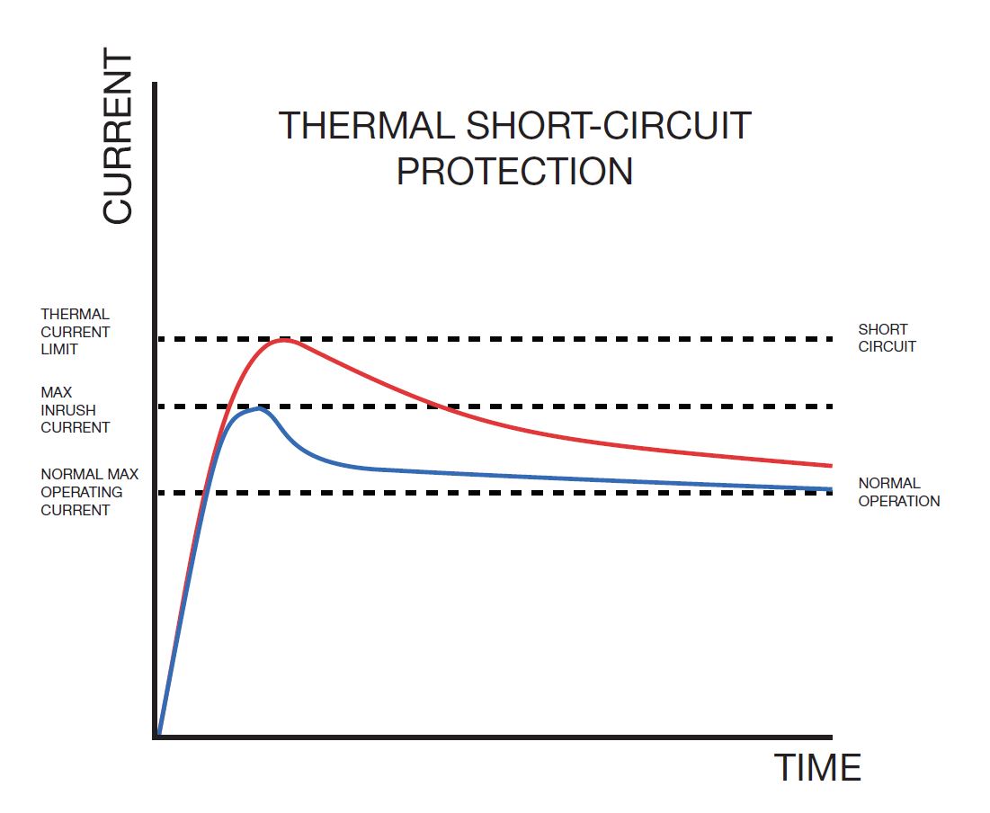
Thermal SCP utilizes series device called a thermistor. As current through it rises, its resistance increases, which acts to throttle the current to a safe level. When the short circuit is removed, the sensor requires a cool down period before it can resume normal function. This is a crude form of short-circuit protection; modern 3-wire sensors no longer employ this method but some older types or some from lesser-known manufacturers may still be using it. One potential advantage for thermal SCP is that it has an inherent time delay that allows for a slightly longer, larger inrush current. This may be helpful in starting some high inrush loads like larger relays or incandescent lamps. However, in most cases today there is no need for a sensor to directly pilot loads like this. Most sensors today have a PLC input as a load.

Thermal Short-Circuit Protection

Latching solid state SCP was common in the past but today is less widely used. When the output current exceeds a defined threshold, the output circuit opens, stopping the flow of current. To reset the sensor after the fault, power to the sensor must be cycled (interrupted and re-applied). This can create a nuisance if the fault is intermittent, because someone has to disconnect and reconnect the sensor to reset it. However, at least the fault condition is captured every time it occurs.

Latching Short-Circuit Protection.JPG

Pulsing solid state SCP is used in most of today’s high-performance sensor designs. The sensor monitors the output for a short circuit and interrupts it the moment the current exceeds the design threshold. Subsequently, the electronics will start to continuously attempt to close the output to see if the fault has been removed. If not, it keeps removing and reapplying power to the output in a “pulsing” manner. If there is an intermittent fault, the sensor will resume normal function when the fault goes away. Sometimes this is called “automatic reset” (as opposed to latching SCP, which is manual reset). Automatic reset can be helpful, or it can be a nuisance. Because the fault isn’t latched, it may be hard to track down which sensor is being shorted if the fault is intermittent. On the plus side, if the fault was one-and-done, the sensor resumes normal function and production continues without further interruption.

Pulsing Short-Circuit Protection

The need to capture short-circuit events is one of the reasons more and more control systems are going with distributed modular I/O blocks using IO-Link. The input port of the block will detect the short circuit and will begin pulsing power to protect the sensor. Although it will automatically reset if the fault is removed, the block will send a fault message to the controller indicating which port was faulted. Note, however, that not all I/O blocks can interrupt a short circuit only at the port level. Many blocks will fault the entire block when only one port is affected. Be sure to ask any potential block supplier how their blocks behave during short-circuit events.

Overload Protection

This circuit monitors the length of time that higher-than-normal (but not short-circuit) load current is flowing. Over time, this can cause overheating of the sensor and subsequent damage. Overload Protection will detect this excessive-current condition and — depending on the type of SCP employed —either reduce current to a safe level (thermal SCP), turn the output off (latching SCP), or pulse the output (pulsing SCP).

Surge Protection

Also sometimes called Overvoltage Protection, this circuit monitors the incoming power supply voltage. When it exceeds the safe threshold, an internal circuit shunts the excessive voltage and clamps the applied voltage to the sensor at a safe level.

Inductive Overvoltage Protection

This circuit prevents sensor output damage from high voltages generated by “back EMF” (Electromotive Force) when an inductive load (like a relay coil) is switched off. Sometimes this is referred to as “inductive kickback”. Since current through an inductor tries to remain constant, the voltage across the inductor rises as the current falls to try to keep it flowing at the same level. The voltage can rise to very high levels, hundreds or thousands of volts, and will appear on the sensor’s output line. (In fact, this generation of high voltage from the collapse of current through an inductor is exactly how automotive spark ignition coils operate.)

So, how does inductive overvoltage protection work? Inside the sensor, a shunt device called a “freewheeling diode” allows the current to continue circulating harmlessly through the inductive load while it decays, preventing the buildup of damaging high voltage.

An Easy Way to Remember PNP and NPN Sensor Wiring

Here’s a simple way remember how to wire up a 3-wire DC PNP or NPN sensor:

PNP = Switched Positive

NPN = Switched Negative

“Switched” refers to which side of the controlled load (relay, small indicator, PLC input) is being switched electrically. Either the load is connected to Negative and the Positive is switched (PNP), or the load is connected to Positive and the Negative is switched (NPN). These diagrams illustrate the differences between the two connections.

Click here for more information about the Sensor Fundamentals training course.

2.14.2018_PNP-v-NPN-Graphic-2-768x1000_update

Boost Size-Change Efficiency with IO-Link Magnetic Encoders and Visualization

In many industries, especially in Packaging, the need to minimize capital equipment costs drives engineers to implement low-cost, manual methods of size change (also called format change) on their machinery. In most cases, this means hand-driven cranks with mechanical dial pointers and/or mechanical revolution counters.

While cost is saved on the procurement side, cost is also shifted over to the operational side. Plant management is left with the task of keeping accurate records of various machine set-ups needed to run different products, as well as the task of training machine operators to perform all machine set-ups correctly. It doesn’t always go as smoothly as expected, and machine reformatting can result in longer downtime than planned, machine stoppages, and possibly excessive scrap.

The key to size-change improvement is capturing the linear movements of the machine components and bringing them into the control system, and then providing “smart” visual feedback to the machine operator during setup. For capturing machine position, a robust and cost-effective magnetic linear encoder is ideal. However, traditional linear encoders deliver an A-B quadrature incremental signal, which requires re-homing upon start-up or after a power loss. What’s needed is an absolute encoder signal, but that brings other challenges such as the cost and complexity of implementing an absolute signal like SSI (Synchronous Serial Interface).

Fortunately, there’s a new encoder interface BML SL1 Absolute Magnetic Encoder with IO-Linkoption that eliminates the problem of non-absolute feedback and the hassle of absolute position signal interface: IO-Link. IO-Link is a multi-vendor, non-proprietary, device-level serial digital interface that can be aggregated onto today’s Ethernet industrial networks. Magnetic linear encoders are now available that feature absolute position indication combined with the ease and convenience of the IO-Link communication protocol.

Now we just need to provide visual feedback to the machine operator regarding which direction and how far to turn the hand cranks. Once smartlight_18x18_300dpiagain, IO-Link provides the answer in the form of an IO-Link-enabled, fully programmable multi-segment LED stack light. When a new machine set up is required, the position parameters are stored in the controller. The controller communicates over IO-Link to the LED stack lights, indicating to the operator which dials need to be turned and in which direction. For example, a horizontally mounted stack light could be lit red on the right half, indicating that the dial needs to be turned to the right. As the position moves closer to the proper setting, the red segments count down until the entire stack light goes green, indicating that the correct position for that axis has been reached. No paper records to maintain and store, and very little training required with the intuitive operator visualization.

For more information about IO-Link linear encoders click here, and to learn more about IO-Link programmable LED stack lights visit www.balluff.com.

In-Cylinder Position Sensing in Electrically Conductive Hydraulic Fluids

The standard for hydraulic fluid in the industry is mineral oil, which is a dielectric medium that does not conduct electricity. Yet environmental concerns have led to the search for alternatives that are less harmful in case of leaks and spills. One development is biodegradable oils, typically with biological origins, often called “bio-oils” for short. They behave in many ways like mineral oil with a key difference in that they can be electrically conductive.

Another alternative hydraulic fluid is water-glycol mixtures, commonly known as the anti-freeze found in your liquid-cooled automobile engine. Water-glycol solutions are used for several reasons, including environmental concerns but more often conditions of extreme heat or extreme cold. They have much lower viscosity than oil, and there are several fluid power application considerations as a result, but water-glycol mixtures, like bio-oils, are electrically conductive.

Image2

So, when it comes to cylinder position sensing, why should we care whether or not the hydraulic fluid is electrically conductive? Well, because it could come back to bite us if we put an incompatible position sensing technology into a cylinder that is filled with a conductive fluid.

I recently met an engineer who’d run into this exact situation. A hydraulic cylinder was ordered from the manufacturer with an “integrated position feedback sensor.” The feedback sensor turned out to be a resistive potentiometric type, in other words, a linear potentiometer or “pot.” The entire length of the resistive material is “wetted” inside the cylinder, along with the traveling “wiper” that moves with the piston. In typical applications with non-conductive, mineral-based hydraulic fluid, this works fine (although linear pots do tend to be somewhat fragile and do wear out over time). However, when the resistive material and wiper is wetted in a conductive liquid, all kinds of wrong start happening. The signal becomes very erratic, unstable, and lacks resolution and repeatability. This is because the fluid is basically short-circuiting the operation of the open-element linear potentiometer.

This caused quite a headache for the engineer’s customer and subsequently for the engineer. Fortunately, a replacement cylinder was ordered, this time with a non-contact magnetostrictive linear position sensor. The magnetostrictive sensor is supplied with a pressure-rated, protective stainless steel tube that isolates the electrical sensing element from the hydraulic medium. The position marker is a magnet instead of a wiper, which the sensor can detect through the walls of the stainless steel pressure tube. So, a magnetostrictive sensor is absolutely unaffected by the electrical properties of the hydraulic medium.

A magnetostrictive linear position sensor carries a lot of performance and application advantages over linear pots that make them a superior technology in most applications, but when it comes to conductive hydraulic fluids they are definitely the preferred choice.

To learn more about linear position sensors visit www.balluff.com.

Absolute Position for Incremental Systems

In linear motion applications, it is often desirable to eliminate the need to make a homing run to re-acquire the reference position for an incremental linear encoder. The homing routine may need to be eliminated to save processing time, or it may not be practical…for example, if the machine can’t be moved following a loss of power due to some mechanical consideration. Additionally, to reduce costs and simplify system design, it would also be helpful to eliminate the need for home and limit switches.

Absolute linear encoders offer an upgrade path, however they also require changes on the controller side to more costly and difficult-to-implement serial interfaces like Biss C, EnDat®, SSI, and others.  These obstacles have limited the use of absolute encoders in the majority of linear motion applications.

Recently, an innovative encoder interface called Absolute Quadrature brings absolute encoder functionality to systems with controllers designed to accept a simple and commonly used A-B quadrature incremental interface.

This demonstration video from In-Position Technologies highlights the functionality and advantages of upgrading incremental positioning systems with an Absolute Quadrature encoder.

To learn more about our Absolute Quadrature encoder, visit www.balluff.com.

External Position Feedback for Hydraulic Cylinders

The classic linear position feedback solution for hydraulic cylinders is the rod-style magnetostrictive sensor installed from the back end of the cylinder. The cylinder rod is gun-drilled to accept the length of the sensor probe, and a target magnet is installed on the face of the piston. A hydraulic port on the end cap provides installation access to thread in the pressure-rated sensor tube. This type of installation carries several advantages but also some potential disadvantages depending on the application.

EDITED Image_HF
Position Sensor Mounted Internally in a Hydraulic Cylinder
(Image credit: Cowan Dynamics)

Advantages of in-cylinder sensor mounting include:

  • Simplicity. The cylinder manufacturer “preps” the cylinder for the sensor and may install it as an extra-cost option.
  • Ruggedness. The sensor element is protected inside the cylinder. Only the electronics head is exposed to the rigors of the industrial environment.
  • Compactness. The sensor is contained inside the cylinder, so it does not add to the cross-sectional area occupied by the cylinder.
  • Direct Position Measurement. Because the target magnet is mounted on the piston, the sensor is directly monitoring the motion of the cylinder without any interposing linkages that might introduce some position error, especially in highly dynamic, high-acceleration / deceleration applications.

Potential disadvantages of in-cylinder sensor mounting may include:

  • Sensor Cost. Cylinder-mounted position sensors require a rugged, fully-sealed stainless-steel sensor probe to withstand the dynamic pressures inside a cylinder. This adds some manufacturing cost.
  • Cylinder Cost. The procedure of gun-drilling a cylinder rod consumes machine time and depletes tooling, adding manufacturing cost over a standard cylinder. Refer to additional comments under Small Cylinder Bores / Rods below.
  • Cylinder Delivery Time. Prepping a new cylinder for a sensor adds manufacturing time due to additional processing steps, some of which may be outsourced by the cylinder manufacturer, increasing overall shipping and handling time.
  • Overall Installed Length. Because the sensor electronics and cabling protrude from the back end of the cylinder, this adds to the overall length of the installed cylinder. Refer to additional comments under Small Cylinder Bores / Rods below.
  • Service Access. In case sensor repair is required, there must be sufficient clearance or access behind the cylinder to pull out the full length of the sensor probe.
  • Small Cylinder Bores / Rods. Some cylinder bores and rod diameters are too small to allow for gun-drilling a hole large enough to install the ~10.2 mm diameter sensor tube and allow for proper fluid flow around it. In tie rod cylinders, the distance between the rod nuts may be too small to allow the flange of the position sensor to fully seat against the O-ring. In these cases, a mounting boss must be provided to move the mounting position back past the tie rods. This adds cost as well as increases overall installed length.

Edited Image 2

In cases where the advantages of in-cylinder mounting are outweighed or rendered impractical by some of the disadvantages, an externally-mounted position sensor can be considered. The list of advantages and disadvantages looks similar, but reversed.

FINAL Profile transducer - hydraulic frame piercing press_HF
Position Sensor Mounted Externally on Hydraulically-Actuated Equipment

Advantages of external sensor mounting include:

  • Sensor Cost. Externally-mounted magnetostrictive position sensors are typically made from an aluminum extrusion and die-cast end caps with gaskets, saving cost compared to all-stainless-steel welded and pressure-rated construction.
  • Cylinder Cost. The cylinder can be a standard type with no special machining work needed to accommodate installation of the sensor.
  • Cylinder Delivery Time. Since no additional machine work is needed, the cylinder manufacturer can deliver within their standard lead time for standard cylinders.
  • Overall Installed Length. Typically, the external sensor is mounted in parallel to the cylinder, so overall length is not increased.
  • Service Access. The externally-mounted sensor is easily accessible for service by simply unbolting its mounting brackets and pulling it off the equipment.

Disadvantages of external sensor mounting may include:

  • Complexity. The machine designer or end user must provide the means to mount the sensor brackets and the means to position a floating magnet target over the sensor housing. Alternatively, a captive sliding magnet target may be used with a length of operating rod and swivel attachment hardware.
  • Exposure to Damage. Unless guarded or installed in a protected area, an externally mounted position sensor is subject to being mechanically damaged.
  • Space Requirements. There must be enough empty space around the cylinder or on the machine to accommodate the sensor housing and operating envelope of the moving magnetic target.
  • Indirect Position Measurement. Any time a floating target magnet is mounted to a bracket, there is the potential for position error due to the bracket getting bent, flexing under acceleration / deceleration, mounting bolts loosening, etc. In the case of operating rods for captive sliding magnets, there will be some mechanical take-up in the swivel joints upon change of direction, adding to position hysteresis. There is also the potential for rod flexing under heavy acceleration / deceleration – particularly when the rod is acting under compression vs. tension. Take note of the amount of sliding friction of the captive magnet on the sensor rails; some sensor magnet designs offer high friction and stiff resistance to movement that can increase operating rod deflection and resultant position error.

In conclusion, be sure to consider all aspects of an application requiring cylinder position feedback and choose the approach that maximizes the most important advantages and eliminates or minimizes any potential disadvantages. It may be that an externally-mounted position sensor will solve some of the challenges being faced with implementing a traditional in-cylinder application.

For more information about internally- and externally-mounted cylinder position sensors, visit www.balluff.com.

Real-Time Optical Thickness Gauging for Hot Rolling Mills

An ever-present challenge in hot rolling operations is to ensure that the material being produced conforms to required dimensional specifications. Rather than contact-based measurement, it is preferred to measure the material optically from a standoff position.

Light band gauging station in hot strip rolling operation detects material thickness in real time.

In some instances, this has been accomplished using two ganged analog optical lasers, each detecting opposite sides of the material being measured. Through mathematical subtraction, the difference representing thickness could be determined. One difficulty of the approach is the need to put a sensor both above and below the material under inspection.  The sensor mounted below could be subjected to falling dirt and debris. Further, only a single point on the surface could be measured.

A new approach uses a scanning laser to create a band of light that is used to directly measure the thickness of the material.  An analog or digital IO-Link signal represents the measured thickness to a resolution of 0.01mm with a repeat accuracy between 10μm to 40μm depending on distance between emitter and receiver.  What’s more, the measurement can be taken even on red-hot metals. The illustration above shows a flat slab but the concept works equally well or better on products with a round profile.

To learn more visit www.balluff.us