The life sciences industry has stringent quality demands for its manufacturing processes due to the nature of its products, which directly impact human health and life. These demands include but are not limited to regulatory compliance, quality control and assurance, sterility and cleanliness, precision and accuracy, traceability, and product stability. The life sciences are also no exception to any other industry in the necessity for continuous improvement and efficiency in their manufacturing processes. As such, businesses in this sector constantly seek out automation solutions to satisfy these demands, with potential use cases for a range of sensing technologies. This industry makes extensive use of the most common sensing technologies, including capacitive, photoelectric, and inductive sensors.
Capacitive sensors
Capacitive sensing relies on the capacitance (the ability to store an electric charge) of material or media to provide an accurate and reliable detection reading. When an object approaches a capacitive sensor, it will interfere with the electrical field of the sensor: If the object is a conductor, it will absorb some of the field’s energy; if it is a dielectric (non-conductor), it will cause a displacement of the electrical field. You can then detect and measure the change. This principle allows capacitives great versatility in sensing applications, some of the most sophisticated applications using certain sensors that can ignore multiple layers of material or media. This is especially useful in the life sciences industry, as many businesses in the sector have complex manufacturing processes that provide challenges for certain automation solutions, such as media-level detection. Standard capacitive sensors can also be useful for general part and product detection as well, depending on the material.
Potential life science applications include:
-
- Bioreactor level detection
- Packaging fill level detection
- Product count detection
- Waste/reagent tank level detection
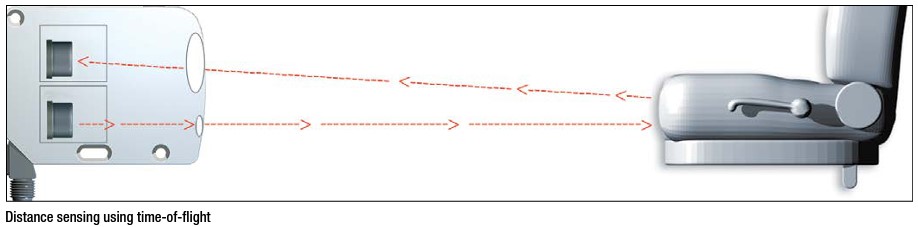
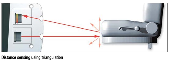
Photoelectric sensors
Photoelectric sensors use light to detect objects and have the following three primary categories:
-
- Through-beam sensors, which use an emitter and receiver to determine object presence by the absorbance or amplification of the emitted light
- Diffuse beam sensors, where the emitter and receiver are in the same housing and light reflects off the object
- Retro-reflective beam sensors, which operate similarly to diffuse but use a fixed special reflector to send polarized light back to the receiver
In addition to these categories and several product variants in each category, photoelectrics come in a variety of housing options that provide great versatility in sensing applications.
Businesses in the life sciences industry can capitalize on photoelectric sensing technology for highly precise measurements and specialized sensors for liquid detection through certain containers and vessels. Photoelectrics can also easily be applied for part and consumable detection.
Potential life science applications include:
-
- Pipette volume detection
- Product cap detection
- Packaging film detection
- Liquid presence in clear tubing
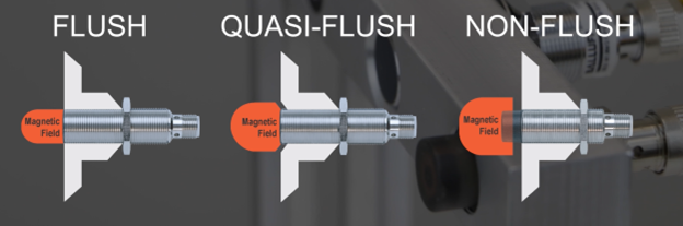
Inductive sensors
Inductive sensors use a coil to generate an electromagnetic field from the sensor head. This field induces eddy currents in objects that come within range of this field, specifically metallic objects. This will cause a change in the magnetic field, which the sensor will measure and detect. Businesses that operate in the life science industry don’t exclusively deal with liquid, media-level, and plastic part detection. Many are also suppliers of sophisticated equipment and instrumentation designed for specific tasks, and these devices must operate reliably through daily cyclical usage, where inductive sensors can ensure they are secure and operate correctly while in use by scientists and technicians.
Potential life science applications include:
-
- Centrifuge lid closure detection
- Robotic arm positioning
- Device speed detection
Applying a few of the most common sensing technologies can satisfy various demands for businesses within the life sciences industry. Companies across all industries share several needs when it comes to gauging the perfect solution for their automation needs, but those in this industry are additionally reliant on highly accurate and precise sensing, sensors that are exceptional in quality and reliability and are customizable to their specific application.