When is a Weld Field Immune Sensor Needed?

When the topic of welding comes up we know that our application is going to be more challenging for sensor selection. Today’s weld cells typically found in tier 1 and tier 2 automotive plants are known to have hostile environments that the standard sensor cannot withstand and can fail regularly. There are many sensor offerings that are designed for welding including special features like Weld Field Immune Circuitry, High Temperature Weld Spatter Coatings and SteelFace Housings.

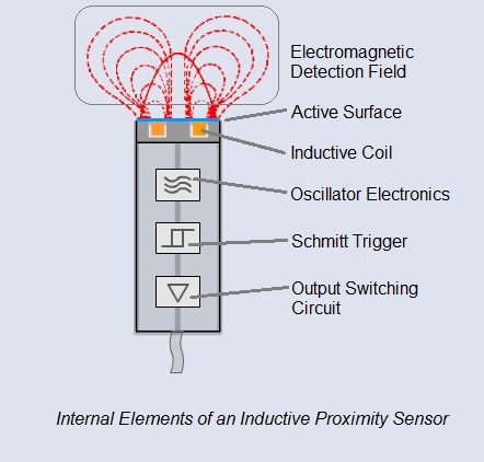
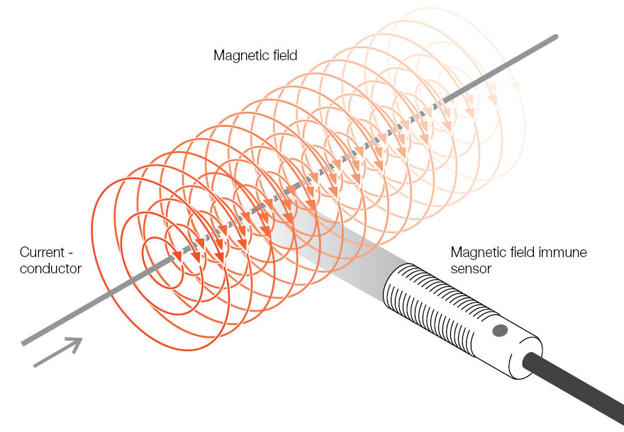
For this SENSORTECH topic I would like to review Weld Field Immune (WFI) sensors. Many welding application areas can generate strong magnetic fields. When this magnetic field is present a typical standard sensor cannot tolerate the magnetic field and is subject to intermittent behavior that can cause unnecessary downtime by providing a false signal when there is no target present. WFI sensors have special filtering properties with robust circuitry that will enable them to withstand the influence of strong magnetic fields.

WFIWFI sensors are typically needed at the weld gun side of the welding procedure when MIG welding is performed. This location is subject to Arc Blow that can cause a strong magnetic field at the weld wire tip location. This is the hottest location in the weld cell and typically there is an Inductive Sensor located at the end of this weld tooling.

So as you can see if a WFI sensor is not selected where there is a magnetic field present it can cause multiple cycle time problems and unnecessary downtime. For more information on WFI sensors click here.

Do’s and Don’ts For Applying Inductive Prox Sensors

Inductive proximity sensor face damage
Example of proximity sensor face damage

In my last post (We Don’t Make Axes Out of Bronze Anymore) we discussed the evolution of technologies which brought up the question, can a prox always replace a limit switch?  Not always.  Note that most proxes cannot directly switch large values of current, for example enough to start a motor, operate a large relay, or power up a high-wattage incandescent light.   Being electronic devices, most standard proxes cannot handle very high temperatures, although specialized hi-temp versions are available.

A prox is designed to be a non-contact device.  That is, it should be installed so that the target does not slam into or rub across the sensing face.  If the application is very rough and the spacing difficult to control, a prox with more sensing range should be selected.  Alternately, the prox could be “bunkered” or flush-mounted inside a heavy, protective bracket.  The target can pound on the bunker continuously, but the sensor remains safely out of harm’s way.

If direct contact with a sensor absolutely cannot be avoided, ruggedized metal-faced sensors are available that are specifically designed to handle impacts on the active surface.

Be sure to consider ambient conditions of the operating environment.  High temperature was mentioned earlier, but other harsh conditions such as disruptive electrical welding fields or high-pressure wash-down can be overcome by selecting proxes specially designed to survive and thrive in these environments.

Operationally, another thing to consider is the target material.  Common mild carbon steel is the ideal target for an inductive prox and will yield the longest sensing ranges with standard proxes.  Other metals such as aluminum, brass, copper, and stainless steel have different material properties that reduce the sensing range of a standard prox.  In these cases be sure to select a Factor 1 type proximity sensor, which can sense all metals at the same range.

We Don’t Make Axes Out of Bronze Anymore

Every technology commonly in use today exists for a reason.   Technologies have life cycles: they are invented out of necessity and are often widely used as the best available solution to a given technical problem.  For example, at one time bronze was the best available metallurgy for making long-lasting tools and weapons, and it quickly replaced copper as the material of choice.  But later on, bronze was itself replaced by iron, steel, and ultimately stainless steel.

When it comes to detecting the presence of an object, such as a moving component on a piece of machinery, the dominant technology used to be electro-mechanical limit switches.  Mechanical & electrical wear and tear under heavy industrial use led to unsatisfactory long-term reliability.  What was needed was a way to switch electrical control signal current without mechanical contact with the target – and without arcing & burning across electrical contacts.

Example of an inductive proximity sensor

Enter the invention of the all-electronic inductive proximity sensor.  With no moving parts and solid-state transistorized switching capability, the inductive proximity sensor solved the two major drawbacks of industrial limit switches (mechanical & electrical wear) in a single, rugged device.  The inductive proximity sensor – or “prox” for short – detects the presence of metallic targets by interpreting changes in the high-frequency electro-magnetic field emanating from its face or “active surface”.  The metal of the target disrupts the field; the sensor responds by electronically switching its output ON (target present) or OFF (target not present). The level of switched current is typically in the 200mA DC range, which is enough to trigger a PLC input or operate a small relay.

In my next post, I will explain the do’s and don’ts for applying inductive prox sensors.

Meeting the Challenges of Precision Sensing: Very Small Target Displacement

Fundamental application problem: Inductive prox sensor is latching on (or…failing to turn on)

  • The prox sensor gap is set to turn on when the target approaches, but it does not turn off when the target recedes (latching on)
  • The prox gap is opened up until sensor turns off at maximum target approach, but it fails to detect the target upon the next approach cycle
  • The prox sensor gap is set to turn on when the target approaches, but later on the operation becomes intermittent (prox fails to reliably detect the target)

Solution: High-performance miniature inductive prox sensor

Critical sensing performance specifications:

o   Low variation of switch point from sample to sample
o   Tight repeat accuracy of switch point
o   Low temperature drift of switch point
o   Low maximum hysteresis (distance between switch-on to switch-off)

Continue reading “Meeting the Challenges of Precision Sensing: Very Small Target Displacement”

Basic Operating Principle of an Inductive Proximity Sensor

Did you ever wonder how an Inductive Proximity Sensor is able to detect the presence of a metallic target?  While the underlying electrical engineering is sophisticated, the basic principle of operation is not too hard to understand.

At the heart of an Inductive Proximity Sensor (“prox” “sensor” or “prox sensor” for short) is an electronic oscillator consisting of an inductive coil made of numerous turns of very fine copper wire, a capacitor for storing electrical charge, and an energy source to provide electrical excitation. The size of the inductive coil and the capacitor are matched to produce a self-sustaining sine wave oscillation at a fixed frequency.  The coil and the capacitor act like two electrical springs with a weight hung between them, constantly pushing electrons back and forth between each other.  Electrical energy is fed into the circuit to initiate and sustain the oscillation.  Without sustaining energy, the oscillation would collapse due to the small power losses from the electrical resistance of the thin copper wire in the coil and other parasitic losses.

 Inductive proximity sensor cutaway with annotation Continue reading “Basic Operating Principle of an Inductive Proximity Sensor”

Are you taking a chance with low-cost sensors?

Don’t take chances with low-cost sensors. Some companies have been severely scaling back on sensor quality to meet price targets. Be on the lookout for these telltale signs of poorly engineered or manufactured sensors:

  • Varying sensing distance: to drive out costs, some manufacturers are eliminating the final distance calibration step. This means the actual sensing range can vary up to 30% from the specifications.
  • Temperature compensation: affecting mostly inductive proximity sensors, this is one of the more technical areas of sensor design. Special circuits and design methods eliminate the large operating distance variation seen with some low-cost sensors.
  • Adequate electrical protection: there are numerous methods to protect a sensor’s output circuit, not all are created equal. Many do not take into account overvoltage, overcurrent, short-circuit, reverse supply polarity, mis-wiring, and energy backfeed from the load.
  • EMI resistance: influence from electro-magnetic interference (EMI) noise can cause false triggers leading to machine malfunctions. It takes years of experience and testing to make sensors that will operate reliably near motors and drives.

Fortunately, there is an answer to these potential problems: the Global line of sensors offered by a reliable sensor manufacturer with decades of proven experience. These products are not built down to price, but instead are built up to the highest standards in the industry. By utilizing highly automated product lines and funneling usage to fewer part numbers with broader application potential, the Global line is one of the most cost-effective sensors programs available today, and without sacrificing any quality or reliability. Bottom line? You don’t need to sacrifice quality or reliability in order to meet your cost budget. For more information, see the entire Global line here.

global

Meeting the Challenges of Precision Sensing: High Acceleration Machinery

Challenge: High Acceleration Machine Movement

Fundamental application problem: Anything mounted to the moving mechanism must be low mass

  • Added mass reduces acceleration capability of a given motor & drive system
  • Added mass increases motor and drive size requirements to meet acceleration specs, driving costs higher
  • Larger motors increase energy consumption, which makes the machine less competitive in the market
  • Any space taken up by sensors reduces space available for tooling and work-in-process
  • Conventional prox sensors and brackets are much too large and heavy to address these requirements

Solution: Incredibly miniaturized, self-contained inductive proximity sensors

  • Tiny size = inherently low mass
  • Correspondingly tiny mounting brackets = inherently low mass
  • Totally self-contained electronics = zero space taken up by separate amplifier
  • Miniaturization of sensors allows no-compromise installation in compact tooling
  • Additional tooling sensors enhance the level of high-end machine automation/control that can be achieved

Stay tuned to this space for more precision sensing challenges and solutions. Miniaturized sensors are also available in photoelectric, capacitive, magnetic cylinder, ultrasonic, and magnetic encoder. Click here to see the whole mini family.

Sensors Reduce Downtime in Welding Applications

Sensors in welding cells are subject to failure because, although they are intended to be non-contact devices, they tend to be located directly in the middle of the welding process. Conditions such as damage by direct mechanical impact, erosion by hot welding slag, false tripping by accumulated slag, and high intermittent heat cause conventional sensors to fail at an excessive rate. In a previous blog post we discussed our three-step protection process.

bunkerproxProperly bunkering and protecting sensors will prolong their service life and reduce downtime. Ideally, this strategy is implemented during the design and construction of the weld cell by the equipment builder in response to buyer demands for increased process reliability. But what about currently existing production equipment that originally was built to a lower standard that is plagued with issues? It can be very difficult for a plant to find the time and personnel resources to go back and address problematic applications with better sensor mounting solutions. The job of retrofitting an entire weld cell with proper sensor protection can take two experienced people up to eight hours or more.

Continue reading “Sensors Reduce Downtime in Welding Applications”

4mm Is The New 2mm

When I began working in the industrial sensor industry back in the mid-’90s, the standard sensing range for a size M12 flush-mount inductive proximity sensor was 2.0 mm.  Advances in sensor technology later brought about so-called “Extended Range” proxes, with M12 flush-mount proxes rated at 4.0 mm nominal sensing distance.  Another popular term for these extended range proxes is “2X”, as in “Two Times” the standard sensing range.

Today, competition and time has brought down the prices of most 2X sensors close to or equal to the prices for standard “1X” sensors.  As a result, there’s a large and growing industry trend to just go ahead and standardize on 2X sensors.  And why not?  If the cost is essentially the same, dollar for dollar a sensor with more range is a more versatile sensor.  The availability of longer range in smaller housings is driving migration from M18 bodies to M12 bodies, and from M12 housings to M08 housings.  This saves money and helps reduce the size and weight of modern machinery.

Continue reading “4mm Is The New 2mm”

Inductive Sensor Correction Factor

Some applications have multiple materials that have to be detected. When specifying a standard inductive proximity sensor the first question asked is, “what is the target material that will need to be detected.” In my previous post, I indicated that the ideal target for an inductive sensor is a target made from mild steel. This is correct; however, an inductive sensor can also detect non-ferrous materials but a correction factor has to be determined into the rated operating distance of your selected sensor. For example, if you select a sensor that has 4mm of operating distance (Rated Operating Distance), and the target is aluminum, we would multiply a correction factor of 0.30-0.45 to get the new rated operating distance of your sensor (1.2mm -1.8mm). Due to the aluminum’s non-ferrous material we can no longer achieve the 4mm rated operating distance in proximity to the aluminum target.

Continue reading “Inductive Sensor Correction Factor”