Stop Industrial Network Failures With One Simple Change

Picture1

It’s the worst when a network goes down on a piece of equipment.  No diagnostics are available to help troubleshooting and all communication is dead.  The only way to find the problem is to physically and visually inspect the hardware on the network until you can find the culprit.  Many manufacturers have told me over the past few months about experiences they’ve had with down networks and how a simple cable or connector is to blame for hours of downtime.
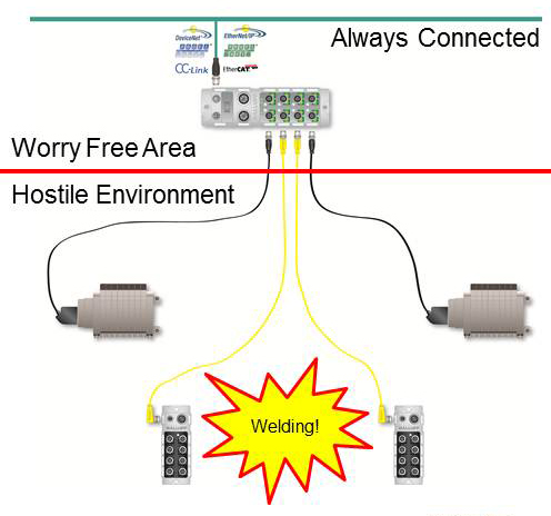
2013-08-19_Balluff-IO-Link_Mexico_Manufactura-de-Autopartes_healywBy utilizing IO-Link, which has been discussed in these earlier blogs, and by changing the physical routing of the network hardware, you can now eliminate the loss of communication.  The expandable architecture of IO-Link allows the master to communicate over the industrial network and be mounted in a “worry-free” zone away from any hostile environments.  Then the IO-Link device is mounted in the hostile environment like a weld cell and it is exposed to the slag debris and damage.  If the IO-Link device fails due to damage, the network remains connected and the IO-Link master reports detailed diagnostics on the failure and which device to replace.  This can dramatically reduce the amount of time production is down.  In addition the IO-Link device utilizes a simple sensor cable for communication and can use protection devices designed for these types of cables.  The best part of this is that the network keeps communicating the whole time.

If you are interested in learning more about the benefits that IO-Link can provide to manufacturers visit www.balluff.us.

Direct load position sensing with secondary feedback encoders

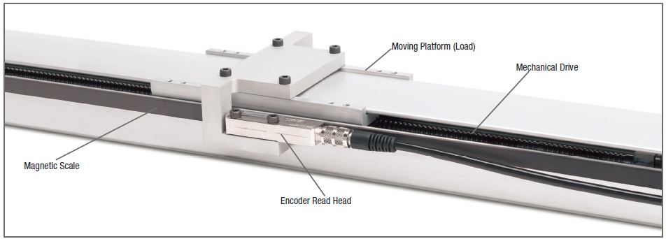
Motion control system designers have found a way to eliminate or reduce common sources of position error, such as mechanical backlash, non-linearity, and hysteresis.  The method is called direct load position sensing and it employs linear encoders as a source of secondary position feedback.  Secondary feedback encoders supplement the indirect position measurement taken by a rotary shaft encoder by measuring the position of the moving load directly.

This method can save money by delivering the specified motion system performance at lower initial cost, and helps maintain system performance over time by getting around the problem of mechanical wear and tear degrading the accuracy of position measurements taken at the motor.

If you’d like to know more, there’s a White Paper available called “Motion Control Primer: Direct load position sensing with secondary feedback encoders”.

linear-actuator-with-encoder

Sacrificing for the Greater Good

Environments with debris and caustic agents, wear down equipment exponentially. When a cell goes down, every minute counts to get production up and running.  An accessory like a cordset is important for operations, and can frustrate technicians when it fails. Cordsets do not last forever in this environment and to help save money, time and work, we came up with the concept of a “sacrificial cable.” The basic idea is to install a double-ended cable under 2 meters to help in situations where cables are placed in surroundings which will destroy the cable.  A sacrificial cable’s main function is to save time reducing cable replacement downtime and money.

Sacrifice Cordset Solution: Used in extremely rugged applications to reduce cordset replacement downtime

hrcable

A sacrificial cable does not have to be a specialty cable with a custom jacket; it could just be a 1 meter PVC cable that will get changed out often. The idea is that by placing a sacrificial cable in a problematic area and connecting it to a longer length cable this will allow maintenance to have a shorter down time when changing out failures less.  This is accomplished with travel around the cell following a cable run and less maintenance expense in labor.

Continue reading “Sacrificing for the Greater Good”

Linear Feedback Sensor Applications: The Three M’s

Applications for linear feedback sensors are numerous and varied.  Likewise, linear feedback sensors are available in numerous form factors and with a wide variety of performance characteristics.  Matching your application to the most appropriate sensor can be a daunting proposition.

When choosing the right linear feedback sensor, it is helpful to first define the job the sensor is being tasked to do.  One way to do this is to think in terms of the three M’s: (M)easuring, (M)onitoring, and (M)otion control.  Linear feedback sensor characteristics that are critical for one of these jobs may not matter as much for another job.  We’re going to take a look at each of these jobs and discuss some of the more important linear feedback selection criteria associated with each.

Measuring:  In measuring applications, the linear feedback sensor is asked to perform the job of an “electronic ruler”.  That is, the sensor is a measuring device used to gauge the size (length, width, thickness, etc.) of the part being produced or processed.  Examples of measuring applications include cut-off saws, or any other cut-length applications.  In such applications, it is absolutely critical for the feedback sensor to provide 1) high accuracy (low non-linearity), and 2) fine resolution. Other factors, such as a fast update rates and highly rugged enclosures are typically not as important in most measuring applications.

Continue reading “Linear Feedback Sensor Applications: The Three M’s”

Fork Sensors – The Ideal Through-Beam

Through-beam sensors are a true time proven solution to many photoelectric applications.  These sensors can detect anything regardless of color, texture or reflectivity, all that needs to happen is the light beam needs to be blocked.  Add an optional aperture and you can detect even the smallest of parts.  With the various light sources available and you can detect small parts (with a laser light) or blast through the harshest of environments with an infrared light source.  These sensors come in several housings or styles for instance tubular (as small as 8mm), block, fiber optic and the fork style sensor.

Through-beam sensors are used in applications that require sensing ranges from 2 millimeters to 100 meters and in some cases longer.  Since these sensors require a light emitter and a receiver that are in separate housings, you have to mount and wire each component separately.  Once mounted you have the task of aligning the receiver to the emitter, which could be a tedious task.  Just imagine trying to line up the devices that use an infrared light source with a working range of 50 meters or even 150 millimeters.

forksensorFork sensors, also referred to, as c slot or u slot, are the ideal through-beam sensor.  First, they are self-contained in one housing so there is no need to align the emitter and receiver.  This is important because in the harsh environments if the sensor is bumped or jarred the receiver and emitter stays aligned.  Secondly, the housings are typically metal offering an extremely robust sensor.  Third, since the sensor is integrated into one housing installation is much easier, one part to mount and only one wiring connection.  These sensors are available from 5mm to 220 mm wide openings.

Continue reading “Fork Sensors – The Ideal Through-Beam”

Automated Assembly Lines Are Shrinking

There is a common trend in the market for smaller more efficient assembly machines. Machine builders and end users are challenged with faster moving, smaller production lines that require smaller sensors and brackets. Balluff has a compete line up of miniaturized sensors. Let’s take a look below of a common challenge for high acceleration machine movement and how miniature sensors can provide a solution.

 miniappCustomer Demands: 

  • Anything mounted to the moving mechanism must be low mass
  • Added mass reduces acceleration  capability of a given motor and drive system
  • Added mass increases motor and drive size requirements to meet acceleration specs (cycle times) driving cost up
  • Large motors increase energy consumption which makes the machine less competitive in the market (less efficient)
  • Conventional sensors and brackets are much too heavy (and usually…too large) to meet this challenge

Solution:

  • minipennyIncredibly miniaturized, self – contained inductive sensors
  • Miniature size = inherently low mass
  • Corresponding tiny brackets = inherently low mass
  • Totally self – contained electronics = zero space taken up by separate amplifier or electronics
  • Miniaturization of sensors allow installation in compact tooling where previously nothing would fit
  • Enhances the level of machine automation/control that customers can achieve for their machines

Stay tuned for more information on how other sensor technologies can be implemented into smaller assembly machines. For more information on mini sensors, click here.

minifamily

My DeviceNet System is Giving Me Heartburn

devicenet analyzerDuring the recent economic downturn, businesses have lost scores of experienced, trained personnel who were very familiar with (among other things) monitoring the health of their DeviceNet System and who may have been responsible for keeping things “up and running”.  Now that business is ramping back up, companies are running lean and we’re all doing “more with less” of everything (including people), the need for rapidly diagnosing issues on a DeviceNet system has increased.  These reasons are exactly why the DeviceNet Analyzer was developed.

The analyzer is a collection of components used for analysis, monitoring and maintaining DeviceNet systems without having to call a third-party to conduct these procedures. The ROI is amazingly fast after technicians have been trained on the use of this powerful tool for checking DeviceNet and CAN bus installations:

  •  Analyze and track down telegrams with poor signal quality. Check for causes of faults, like missing bus terminations (or too many bus terminations), faulty bus drivers, or trunk and drop lines that are too long.
  • Physical cable troubleshooting is accomplished on a “wire test” function that detects the location of cable breaks and short circuits.  “Weak Spots” like incorrect cable types, lengths, and faulty plugs are also located.
  • Monitor…comparisons can be made at regular or continuous intervals via an online function.  Gradual degradation of system quality can be seen and proactive preventative maintenance can in turn be enacted.

If you have DeviceNet “Heartburn”…there is an Antacid! For more information on the DeviceNet Analyzer, click here or watch the video below.

Back to the Basics on Receptacles – Part 2

In a previous post, I talked about receptacles for automation equipment.  But there are many different types of mounting when it comes to receptacles.  When picking a mounting type, it is based on preference.  Each type of mounting has its good points.  Depending on what else is inside the cabinet, might sway which mounting is preferred.

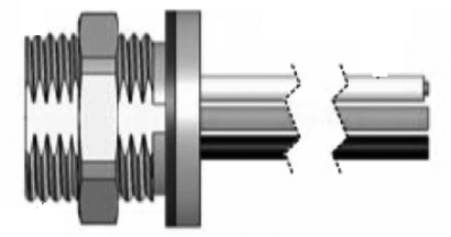
r2_1A popular mounting is front mounting.  Front mounting comes into the panel from the outside of the control cabinet and is secured with lock (jamming) nut on the inside of the cabinet and sealed with an o-ring on the outside of the cabinet (figure to the right).  The o-ring with the lock nut gives the receptacle a tight seal to keep out dust and moisture.  It is one of the easier receptacles to replace since it is installed from the outside of the cabinet.

r2_2Another mounting type is back mounting.   With a back mounting, the threads are on the connector part of the receptacle.  Back mounting is the opposite of the front mounting with the o –ring and jamming nut on the outside of the cabinet.  A back mounting receptacle takes some preplanning.  The receptacle should go into the control cabinet first to make sure there is room for the other components in the cabinet like a power source, PLC or terminals.  If the receptacle needs replaced, then it might require some of the components in the cabinet to be removed to have enough room to remove the receptacle.

Continue reading “Back to the Basics on Receptacles – Part 2”

Tracking low-cost assets with RFID tags…Is it worth it?

First, a lesson in Lexicography

Lexi-what!? Don’t be alarmed. This blog is not as boring as it sounds, especially if you are involved in manufacturing. Lexicography is the art of compiling, writing and editing dictionaries. Sounds like a ton of fun, but let’s move quickly to the point to prevent nausea or inducing sleep. Value, according to dictionary.com when used as a noun, is defined as relative worth, merit, or importance. Notice, the lexicographer mentions nothing about cost.

Tracking valuable assets using RFID within the walls of a plant has become common practice for many organizations. Tracking fork trucks, specialized equipment, machinery and other high cost items are a no-brainer. However, experienced users of RFID technology have realized that it is important to know the location of a high cost asset, but it is paramount to know the location of a high value item.

Defining the VALUE of assets (tools, measurement and calibration devices, specialized machines etc.) can be a tricky game. Conversely, it is not difficult to record the cost of an asset on a balance sheet. A tool which has a cost of $50 doesn’t have a VALUE of $50.

Do you really know what your assets are worth? Is your $50 tool worth hundreds, thousands, or even millions? How is that possible? This is fairly straight forward. If that tool is an integral part in the operation of the manufacturing line then every minute that tool is “missing” is a minute of downtime. How much does a minute of downtime cost your company? How much does an hour of downtime cost your company? Does this tool help your final product conform to standards? What is the cost of nonconformance? What are the financial implications of a product recall? These questions need to be addressed when determining whether or not you should track your assets.

Continue reading “Tracking low-cost assets with RFID tags…Is it worth it?”

The Case for Retrofitting with Advanced Motion Controllers

Over at Machine Design, Bruce Coons with Delta Computer Systems (Battleground, WA) has written an excellent piece entitled “The Case for Retrofitting with Advanced Motion Controllers”.

In the article, Bruce talks about the idea of retrofitting older equipment with new controls.   It’s a great way to save on capital expenditures if the equipment is fundamentally sound but productivity and/or quality are being held back by an obsolete control system.  Definitely worth a read if you have a piece of equipment that could benefit from updated electronics.