The intralogistics industry has made significant investments in automation since 2020. The boom in ecommerce, accelerated by the pandemic, pressured online retailers to improve their warehouse operations through automation. Traditional manufacturers and non-ecommerce (B2B) firms have been slower in automating their intralogistics operations, and penetration is still relatively low. This is rapidly changing, driven by market factors such as labor issues, product individualization, supply chain challenges, higher efficiency/productivity/quality, faster delivery, and wider adoption of ecommerce by B2B firms.
The deeper penetration of automation in intralogistics means that the applications are now using or adapting many of the same technologies and smart manufacturing processes employed in traditional manufacturing: robotics, PLCs and motion controllers, industrial networks, sensors, motors and drives, RFID/code reading, vision systems, human-machine interfaces, automation software, IIoT/Industry 4.0, and more. This blog focuses on the use of sensors, networking, and RFID/code reading in common intralogistics processes:
-
- Conveying and transporting
- Storage and retrieval
- Sorting and picking
Within these areas, there are several key applications. I’ll go into more detail on solutions for each of them:
-
- Object detection
- Controls architecture
- Traceability
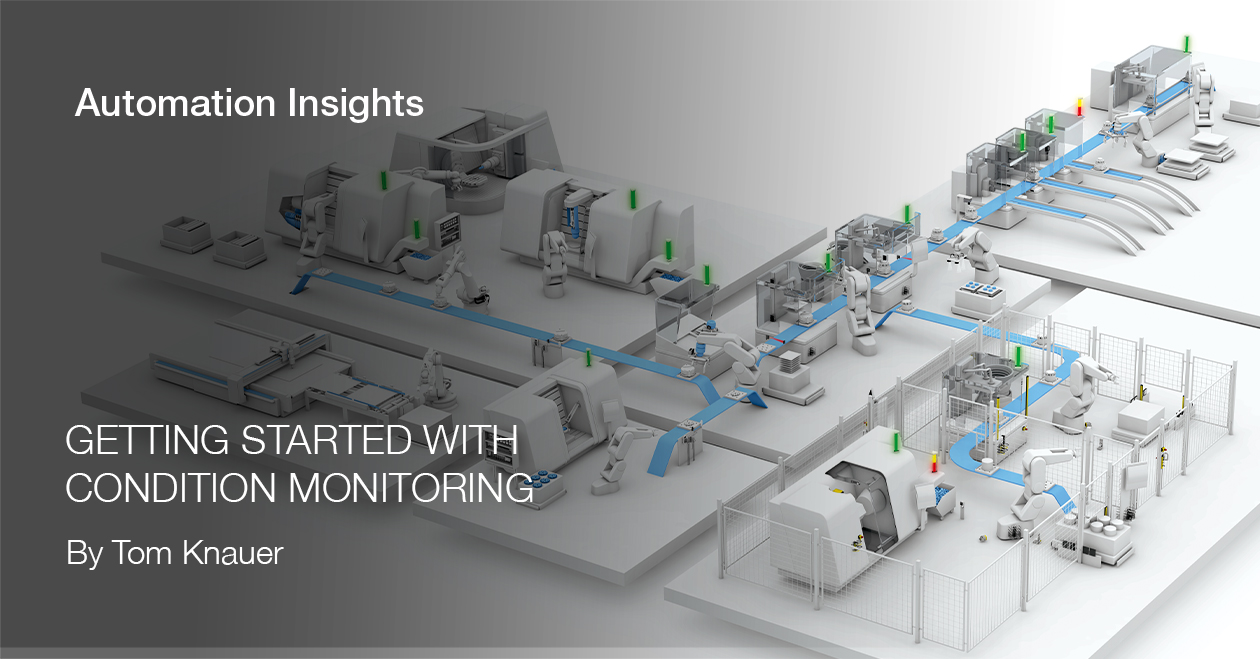
- Condition monitoring

Object detection: Photoelectric, inductive, ultrasonic, and capacitive sensors are used to reliably detect objects on conveyors, container fill levels, and object presence, position, shape, color, distance, or thickness. Photoelectric sensors are often used to detect bottles, totes, or material on conveyors or to detect items in racks or on transporters. Inductive sensors can detect metal objects on conveyors or in racks, but also the position of parts of the equipment to verify position, alignment, or proper operation. While photoelectric or inductive sensors can also detect objects for picking and sorting applications, vision systems are often used when robots are involved in the process.
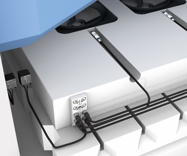
Controls architecture: Connecting sensors and devices to the control system can be time-consuming and complicated, involving long cables, many terminations, and difficult troubleshooting. The automation industry, therefore, uses industrial networking to simplify controls architectures. It is an especially interesting and cost-effective approach for intralogistics because the facilities are often large, with long distances and many sensors. Network blocks and hubs using technologies such as IO-Link make it easy and inexpensive to connect many sensors using common M12 or M8 cables. IO-Link not only gathers standard process data but also provides diagnostic/event and parameter data. This simplifies detecting the individual device status and troubleshooting mistakes in wiring or broken sensors. When implementing automation, especially for large-scale conveying or storage and retrieval systems, companies typically apply a networked controls architecture across most intralogistics processes.
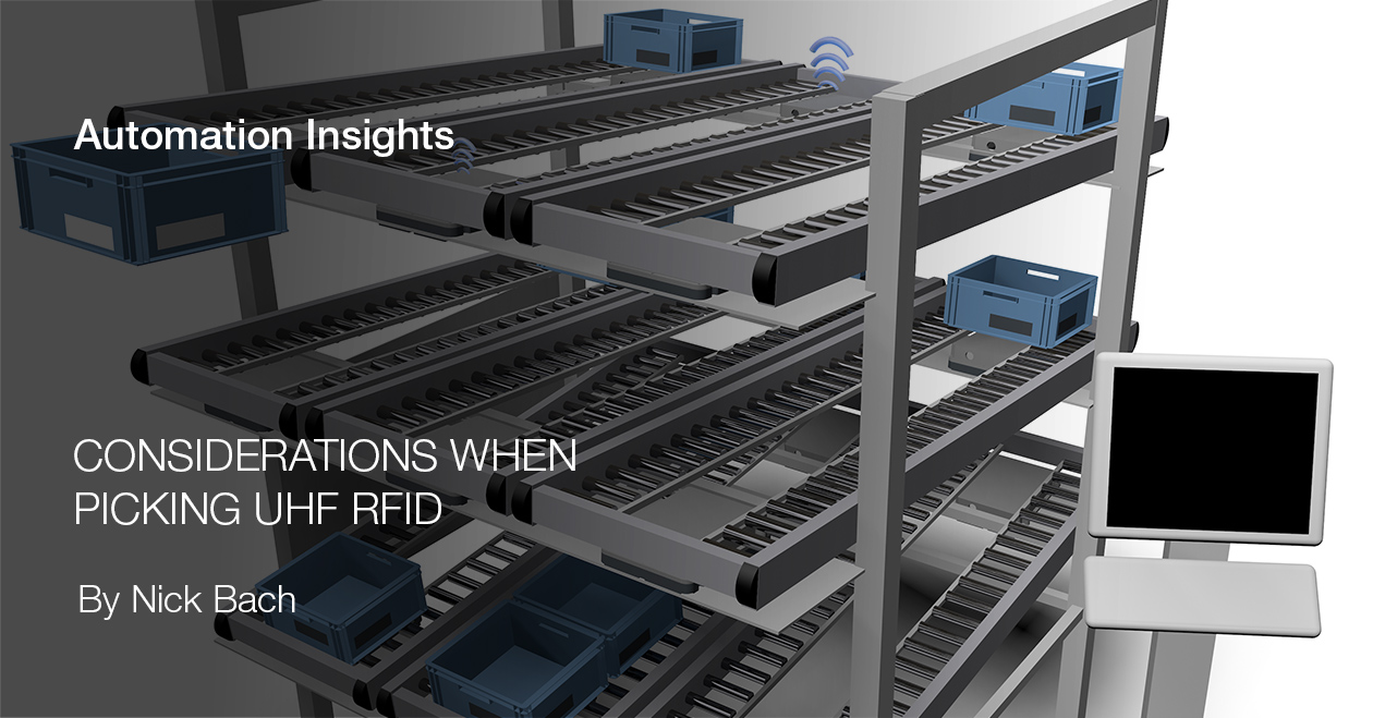
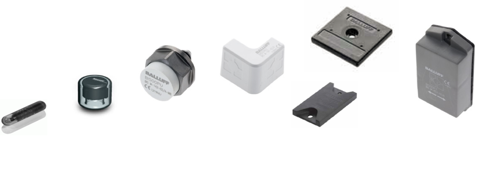
Traceability: Tracking the movement of goods through a facility is a critical part of the intralogistics process. The most used technologies are RFID and code reading; selection depends on the application. RFID is generally available in low (LF), high (HF), and ultra-high (UHF) frequencies. LF and HF RFID are good for short-range part tracking and production control where data needs to be read/written to a single tag at a time (for example, items on a conveyor). UHF RFID systems are better for longer distance detection of multiple tags (for example, tracking pallets through a facility). Coder readers are popular in intralogistics facilities because bar codes are common, simple, and easy to use. Reader technology has evolved to address past challenges such as reading multiple codes at once, imprecise code location, and code type variation. In some cases, companies use code reading for positioning storage systems or navigating AGVs.
Condition monitoring: Reducing unplanned downtime and improving Overall Equipment Effectiveness (OEE) are focus topics in intralogistics automation, and condition monitoring offers a solution to these challenges. A wide variety of sensors are available to detect vibration, temperature, pressure, flow, and humidity to help monitor equipment conditions. This sensor data can be easily gathered through the controls architecture or “add-on” data gateways, with IO-Link offering a wide variety of sensor and gateway choices. The most common intralogistics condition monitoring applications involve motion (motors, gearboxes, bearings, shafts, pumps, fans) for conveyors, storage/retrieval, and transport systems.
The use of automation in intralogistics will continue to grow rapidly as both ecommerce firms and traditional manufacturers seek to optimize their warehouse, conveying, and picking/sorting operations in response to industry and societal trends. These companies are realizing that worker shortages, faster delivery, improved quality, higher efficiency, mass customization, and supply chain issues are best addressed by automation.