Overcoming Challenges in Metal Detection: The Power of Factor 1 Sensors

Standard inductive proximity sensors are used across the automation industry for metal detection applications and are generally reliable in these operations. But issues arise when switching from steel to other metals like copper, brass, or aluminum. A standard inductive sensor may encounter problems in such scenarios. Due to the reduction factor, the standard inductive sensor detects these different metals at different distances. If you had a sensor mounted and set up to sense a steel material but switched to copper, for example, the copper material might be out of the sensor’s range due to this difference in reduction factor, resulting in a missed reading. Factor 1 sensors were created to eliminate this problem.

Reduction factor

The reduction factor is the root cause of variable distance readings with a standard inductive sensor. But what exactly is it? The standard operating range of an inductive proximity sensor is determined by its response to a one-millimeter-thick square piece of mild steel. Other metals like copper and aluminum deviate from this standard range due to differences in material properties. For example, copper has a reduction factor of around 0.4, so it can only be detected at 0.4 times the standard operating range of an inductive proximity sensor.

We can save for later the details of why this occurs, but the key point here is that different material properties cause different reduction factors, which result in different switching distances. The table below shows these different reduction factors and switching distances. Factor 1 sensors take all these variable reduction factors and equalize them to a standard operating distance. This means that you can read anything from copper to steel at the same range, reducing the possibility of missed readings and eliminating the need for repositioning sensors whenever a material change occurs.

When to use Factor 1 sensors

Factor 1 sensors are well-suited for any process that involves different metals. Whether it is automated welding or a packaging conveyor, the factor 1 sensor will keep the material switching ranges uniform. But why is this such a big advantage?

Think about the time spent having to adjust sensor distances. Not only is the task annoying, it also takes up time. Having factor 1 sensors in place will increase the uptime of these processes and eliminate the need for sensor adjustments.

One last benefit to note about factor 1 sensors is that they are inherently weld field immune. The internal construction of the sensor prevents it from being affected by the electromagnetic field generated during welding. This additional immunity allows the sensor to survive in these welding conditions where a typical sensor might fail if it comes in proximity to the weld field.

In the end, you know your application best, but if any of the above benefits resonate with you, it’s time to start thinking about factor 1.

Future Proofing Weld Cell Operations

Weld cells are known for their harsh environments, with high temperatures, electromagnetic field disruptions, and weld spatter debris all contributing to the reduced lifespan of standard sensors. However, there are ways to address this issue and minimize downtime, headaches, and costs associated with sensor replacement.

Sensor selection

Choosing the appropriate sensor for the environment may be the answer to ensuring optimal uptime for a weld cell environment. If current practices are consistently failing, here are some things to consider:

    • Is there excessive weld spatter on the sensor?
    • Is the sensor physically damaged?
    • Is there a better mounting solution for the sensor?

For example, sensors or mounts with coatings can help protect against weld spatter accumulation while specialized sensors can withstand environmental conditions, such as high temperatures and electromagnet interferences. To protect from physical damage, a steel-faced sensor may be an ideal solution for increased durability. Identifying the root cause of the current problem is critical in this process, and informed decisions can be made to improve the process for the future.

Sensor protection

In addition to selecting the correct sensor, further steps can be taken to maximize the potential of the weld cell. The sections below cover some common solutions for increasing sensor lifetime, including sensor mounts and bunkers, and entirely removing the sensor from the environment.

Mounting and bunkering

Sensor mounting enables the positioning of the sensor, allowing for alignment correction and the possibility of moving the sensor to a safer position. Some examples of standard mounting options are shown in image 1. Bunkering is generally the better option for a welding environment, with material thickness and robust metal construction protecting the sensor from physical damage as displayed on the right in image 2. The standard mounts on the left are made of either plastic or aluminum. Selecting a mounting or bunkering solution with weld spatter-resistant coating can further protect the sensor and mounting hardware from weld spatter buildup and fully maximize the system’s lifetime.

Image 1
Image 2

Plunger probes

Using a plunger probe, which actuates along a spring, involves entirely removing the sensor from the environment. As a part comes into contact with the probe and pushes it into the spring, an embedded inductive sensor reads when the probe enters its field of vision, allowing for part validation while fully eliminating sensor hazards. This is a great solution in cases where temperatures are too hot for even a coated sensor or the coated sensor is failing due to long-term, high-temperature exposure. This mechanical solution also allows for physical contact but eliminates the physical damage that would occur to a normal sensor over time.

The solutions mentioned above are suggestions to keep in mind when accessing the current weld cell. It is important to identify any noticeable, repeatable failures and take measures to prevent them. Implementing these measures will minimize downtime and extend the lifetime of the sensor.

Leave a comment for a follow-up post if you’d like to learn about networking and connectivity in weld cells.

Choosing Sensors Suitable for Automation Welding Environments

Standard sensors and equipment won’t survive for very long in automated welding environments where high temperatures, flying sparks and weld spatter can quickly damage them. Here are some questions to consider when choosing the sensors that best fit such harsh conditions:

    • How close do you need to be to the part?
    • Can you use a photoelectric sensor from a distance?
    • What kind of heat are the sensors going to see?
    • Will the sensors be subject to weld large weld fields?
    • Will the sensors be subject to weld spatter?
    • Will the sensor interfere with the welding process?

Some solutions include using:

    • A PTFE weld spatter resistant and weld field immune sensor
    • A high-temperature sensor
    • A photoelectric diffuse sensor with a glass face for better resistance to weld spatter, while staying as far away as possible from the MIG welding application

Problem, solution

A recent customer was going through two sensors out of four every six hours. These sensors were subject to a lot of heat as they were part of the tooling that was holding the part being welded. So basically, it became a heat sink.

The best solution to this was to add water jackets to the tooling to help cool the area that was being welded. This is typically done in high-temperature welding applications or short cycle times that generate a lot of heat.

    • Solution 1 was to use a 160 Deg C temp sensor to see if the life span would last much longer.
    • Solution 2 was to use a plunger prob mount to get more distance from the weld area.

Using both solutions was the best solution. This increased the life to one week of running before it was necessary to replace the sensor. Still better than two every 6 hours.

Taking the above factors into consideration can make for a happy weld cell if time and care are put into the design of the system. It’s not always easy to get the right solution as some parts are so small or must be placed in tight areas. That’s why there are so many choices.

Following these guidelines will help significantly.

The 5 Most Common Types of Fixed Industrial Robots

The International Federation of Robotics (IFR) defines five types of fixed industrial robots: Cartesian/Gantry, SCARA, Articulated, Parallel/Delta and Cylindrical (mobile robots are not included in the “fixed” robot category). These types are generally classified by their mechanical structure, which dictates the ways they can move.

Based on the current market situation and trends, we have modified this list by removing Cylindrical robots and adding Power & Force Limited Collaborative robots. Cylindrical robots have a small, declining share of the market and some industry analysts predict that they will be completely replaced by SCARA robots, which can cover similar applications at higher speed and performance. On the other hand, use of collaborative robots has grown rapidly since their first commercial sale by Universal Robots in 2008. This is why collaborative robots are on our list and cylindrical/spherical robots are not.

Therefore, our list of the top five industrial robot types includes:

    • Articulated
    • Cartesian/Gantry
    • Parallel/Delta
    • SCARA
    • Power & Force Limited Collaborative robots

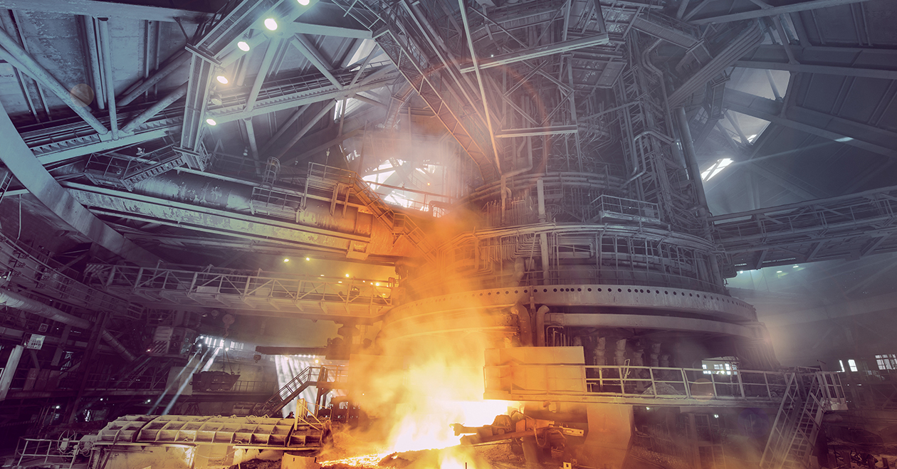
These five common types of robots have emerged to address different applications, though there is now some overlap in the applications they serve. And range of industries where they are used is now very wide. The IFR’s 2021 report ranks electronics/electrical, automotive, metal & machinery, plastic and chemical products and food as the industries most commonly using fixed industrial robots. And the top applications identified in the report are material/parts handling and machine loading/unloading, welding, assembling, cleanrooms, dispensing/painting and processing/machining.
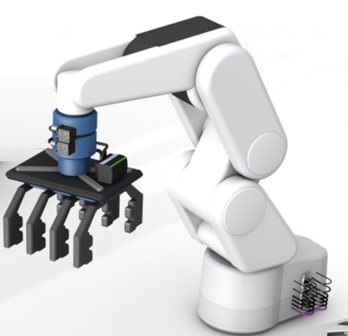
Articulated robots

Articulated robots most closely resemble a human arm and have multiple rotary joints–the most common versions have six axes. These can be large, powerful robots, capable of moving heavy loads precisely at moderate speeds. Smaller versions are available for precise movement of lighter loads. These robots have the largest market share (≈60%) and are growing between 5–10% per year.

Articulated robots are used across many industries and applications. Automotive has the biggest user base, but they are also used in other industries such as packaging, metalworking, plastics and electronics. Applications include material & parts handling (including machine loading & unloading, picking & placing and palletizing), assembling (ranging from small to large parts), welding, painting, and processing (machining, grinding, polishing).

SCARA robots

A SCARA robot is a “Selective Compliance Assembly Robot Arm,” also known as a “Selective Compliance Articulated Robot Arm.” They are compliant in the X-Y direction but rigid in the Z direction. These robots are fairly common, with around 15% market share and a 5-10% per year growth rate.

SCARA robots are most often applied in the Life Sciences, Semiconductor and Electronics industries. They are used in applications requiring high speed and high accuracy such as assembling, handling or picking & placing of lightweight parts, but also in 3D printing and dispensing.

Cartesian/Gantry robots

Cartesian robots, also known as gantry or linear robots, move along multiple linear axes. Since these axes are very rigid, they can precisely move heavy payloads, though this also means they require a lot of space. They have about 15% market share and a 5-10% per year growth rate.

Cartesian robots are often used in handling, loading/unloading, sorting & storing and picking & placing applications, but also in welding, assembling and machining. Industries using these robots include automotive, packaging, food & beverage, aerospace, heavy engineering and semiconductor.

Delta/Parallel robots

Delta robots (also known as parallel robots) are lightweight, high-speed robots, usually for fast handling of small and lightweight products or parts. They have a unique configuration with three or four lightweight arms arranged in parallelograms. These robots have 5% market share and a 3–5% growth rate.

They are often used in food or small part handling and/or packaging. Typical applications are assembling, picking & placing and packaging. Industries include food & beverage, cosmetics, packaging, electronics/ semiconductor, consumer goods, pharmaceutical and medical.

Power & Force Limiting Collaborative robots

We add the term “Power & Force Limiting” to our Collaborative robot category because the standards actually define four collaborative robot application modes, and we want to focus on this, the most well-known mode. Click here to read a blog on the different collaborative modes. Power & Force Limiting robots include models from Universal Robots, the FANUC CR green robots and the YuMi from ABB. Collaborative robots have become popular due to their ease of use, flexibility and “built-in” safety and ability to be used in close proximity to humans. They are most often an articulated robot with special features to limit power and force exerted by the axes to allow close, safe operation near humans or other machines. Larger, faster and stronger robots can also be used in collaborative applications with the addition of safety sensors and special programming.

Power & Force Limiting Collaborative robots have about 5% market share and sales are growing rapidly at 20%+ per year. They are a big success with small and mid-size enterprises, but also with more traditional robot users in a very broad range of industries including automotive and electronics. Typical applications include machine loading/unloading, assembling, handling, dispensing, picking & placing, palletizing, and welding.

Summary­

The robot market is one of the most rapidly growing segments of the industrial automation industry. The need for more automation and robots is driven by factors such as supply chain issues, changing workforce, cost pressures, digitalization and mass customization (highly flexible manufacturing). A broad range of robot types, capabilities and price points have emerged to address these factors and satisfy the needs of applications and industries ranging from automotive to food & beverage to life sciences.

Note: Market share and growth rate estimates in this blog are based on public data published by the International Federation of Robotics, Loup Ventures, NIST and Interact Analysis.

Protecting photoelectric and capacitive sensors

Supply chain and labor shortages are putting extra pressure on automation solutions to keep manufacturing lines running. Even though sensors are designed to work in harsh environments, one good knock can put a sensor out of alignment or even out of condition. Keep reading for tips on ways to protect photoelectric and capacitive sensors.

Mounting solutions for photoelectric sensors

Photoelectric sensors are sensitive to environmental factors that can cloud their view, like dust, debris, and splashing liquids, or damage them with physical impact. One of the best things to do from the beginning is to protect them by mounting them in locations that keep them out of harm’s way. Adjustable mounting solutions make it easier to set up sensors a little further away from the action. Mounts that can be adjusted on three axes like ball joints or rod-and-mount combinations should lock firmly into position so that vibration or weight will not cause sensors to move out of alignment. And mounting materials like stainless steel or plastic can be chosen to meet factors like temperature, accessibility, susceptibility to impact, and contact with other materials.

When using retroreflective sensors, reflectors and reflective foils need similar attention. Consider whether the application involves heat or chemicals that might contact reflectors. Reflectors come in versions, especially for use with red, white, infrared, and laser lights, or especially for polarized or non-polarized light. And there are mounting solutions for reflectors as well.

Considering the material and design of capacitive sensors

Capacitive sensors must also be protected based on their working environment, the material they detect, and where they are installed. Particularly, is the sensor in contact with the material it is sensing or not?

If there is contact, pay special attention to the sensor’s material and design. Foods, beverages, chemicals, viscous substances, powders, or bulk materials can degrade a sensor constructed of the wrong material. And to switch perspectives, a sensor can affect the quality of the material it contacts, like changing the taste of a food product. If resistance to chemicals is needed, housings made of stainless steel, PTFE, and PEEK are available.

While the sensor’s material is important to its functionality, the physical design of the sensor is also important. A working environment can involve washdown processes or hygienic requirements. If that is the case, the sensor’s design should allow water and cleaning agents to easily run off, while hygienic requirements demand that the sensor not have gaps or crevices where material may accumulate and harbor bacteria. Consider capacitive sensors that hold FDA, Ecolab, and CIP certifications to work safely in these conditions.

Non-contact capacitive sensors can have their own special set of requirements. They can detect material through the walls of a tank, depending on the tank wall’s material type and thickness. Plastic walls and non-metallic packaging present a smaller challenge. Different housing styles – flat cylindrical, discs, and block styles – have different sensing capabilities.

Newer capacitive technology is designed as an adhesive tape to measure the material inside a tank or vessel continuously. Available with stainless steel, plastic, or PTFF housing, it works particularly well when there is little space available to detect through a plastic or glass wall of 8mm or less. When installing the tape, the user can cut it with scissors to adjust the length.

Whatever the setting, environmental factors and installation factors can affect the functionality of photoelectric and capacitive sensors, sometimes bringing them to an untimely end. Details like mounting systems and sensor materials may not be the first requirements you look for, but they are important features that can extend the life of your sensors.


Weld Immune vs. Weld Field Immune: What’s the difference? 

In today’s automotive plants and their tier suppliers, the weld cell is known to be one of the most hostile environments for sensors. Weld slag accumulation, elevated ambient temperatures, impacts by moving parts, and strong electromagnetic fields can all degrade sensor performance and cause false triggering. It is widely accepted that sensors will have a limited life span in most plants.

Poor sensor selection does mean higher failure rates which cause welders in all industries increased downtime, unnecessary maintenance, lost profits, and delayed delivery. There are many sensor features designed specifically to withstand these harsh welding environments and the problems that come along with them to combat this.

In the search for a suitable sensor for your welding application, you are sure to come across the terms weld immune and weld field immune. What do these words mean? Are they the same thing? And will they last in my weld cell?

Weld Immune ≠ Weld Field Immune

At first glance, it is easy to understand why someone may confuse these two terms or assume they are one and the same.

Weld field immune is a specific term referring to sensors designed to withstand strong electromagnetic fields. In some welding areas, especially very close to the weld gun, welders can generate strong magnetic fields. When this magnetic field is present, it can cause a standard sensor to perform intermittently, like flickering and false outputs.

Weld field immune sensors have special filtering and robust circuitry that withstand the influence of strong magnetic fields and avoid false triggers. This is also called magnetic field immune since they also perform well in any area with high magnetic noise.

On the other hand, weld immune is a broad term used to describe a sensor designed with any features that increase its performance in a welding application. It could refer to one or multiple sensor features, including:

    • Weld spatter resistant coatings
    • High-temperature resistance
    • Different housing or sensor face materials
    • Magnetic field immunity

A weld field immune sensor might be listed with the numerous weld immune sensors with special coatings and features, but that does not necessarily mean any of those other sensors are immune to weld fields. This is why it is always important to check the individual sensor specifications to ensure it is suitable for your application.

In an application where a sensor is failing due to impact damage or weld slag spatter, a steel face sensor with a weld resistant coating could be a great solution. If this sensor isn’t close to the weld gun and isn’t exposed to any strong magnetic fields, there is really no need for it to be weld field immune. The important features are the steel face and coating that can protect it against impact and weld slag sticking to it. This sensor would be classified as weld immune.

In another application where a sensor near the weld gun side of the welding procedure where MIG welding is performed, this location is subject to arc blow that can create a strong magnetic field at the weld wire tip location. In this situation, having a weld field immune sensor would be important to avoid false triggers that the magnetic field may cause. Additionally, being close to a MIG weld gun, it would also be wise to consider a sensor with other weld immune properties, like a weld slag resistant coating and a thermal barrier, to protect against high heat and weld slag.

Weld field immunity is just one of many features you can select when picking the best sensor for your application. Whether the issue is weld slag accumulation, elevated ambient temperatures, part impact, or strong electromagnetic fields, there are many weld immune solutions to consider. Check the placement and conditions of the sensors you’re using to decide which weld-immune features are needed for each sensor.

Click here for more on choosing the right sensor for your welding application.


Does Your Stamping Department Need a Checkup? Try a Die-Protection Risk Assessment

If you have ever walked through a stamping department at a metal forming facility, you have heard the rhythmic sound of the press stamping out parts, thump, thump. The stamping department is the heart manufacturing facility, and the noise you hear is the heartbeat of the plant. If it stops, the whole plant comes to a halt. With increasing demands for higher production rates, less downtime, and reduction in bad parts, stamping departments are under ever-increasing pressure to optimize the press department through die protection and error-proofing programs.

The die-protection risk assessment team

The first step in implementing or optimizing a die protection program is to perform a die-protection risk assessment. This is much like risk assessments conducted for safety applications, except they are done for each die set. To do this, build a team of people from various positions in the press department like tool makers, operators, and set-up teams.

Once this team is formed, they can help identify any incidents that could occur during the stamping operations for each die set and determine the likelihood and the severity of possible harm. With this information, they can identify which events have a higher risk/severity and determine what additional measures they should implement to prevent these incidents. An audit is possible even if there are already some die protection sensors in place to determine if there are more that should be added and verify the ones in place are appropriate and effective.

The top 4 die processes to check

The majority of quality and die protection problems occur in one of these three areas: material feed, material progression, and part- and slug-out detections. It’s important to monitor these areas carefully with various sensor technologies.

Material feed

Material feed is perhaps the most critical area to monitor. You need to ensure the material is in the press, in the correct location, and feeding properly before cycling the press. The material could be feeding as a steel blank, or it could come off a roll of steel. Several errors can prevent the material from advancing to the next stage or out of the press: the feed can slip, the stock material feeding in can buckle, or scrap can fail to drop and block the strip from advancing, to name a few. Inductive proximity sensors, which detect iron-based metals at short distances, are commonly used to check material feeds.

Material progression

Material progression is the next area to monitor. When using a progressive die, you will want to monitor the stripper to make sure it is functioning and the material is moving through the die properly. With a transfer die, you want to make sure the sheet of material is nesting correctly before cycling the press. Inductive proximity sensors are the most common sensor used in these applications, as well.

Here is an example of using two inductive proximity sensors to determine if the part is feeding properly or if there is a short or long feed. In this application, both proximity sensors must detect the edge of the metal. If the alignment is off by just a few millimeters, one sensor won’t detect the metal. You can use this information to prevent the press from cycling to the next step.

Short feed, long feed, perfect alignment

Part-out detection

The third critical area that stamping departments typically monitor is part-out detection, which makes sure the finished part has come out of the stamping

area after the cycle is complete. Cycling the press and closing the tooling on a formed part that failed to eject can result in a number of undesirable events, like blowing out an entire die section or sending metal shards flying into the room. Optical sensors are typically used to check for part-out, though the type of photoelectric needed depends on the situation. If the part consistently comes out of the press at the same position every time, a through-beam photo-eye would be a good choice. If the part is falling at different angles and locations, you might choose a non-safety rated light grid.

Slug-ejection detection

The last event to monitor is slug ejection. A slug is a piece of scrap metal punched out of the material. For example, if you needed to punch some holes in metal, the slug would be the center part that is knocked out. You need to verify that the scrap has exited the press before the next cycle. Sometimes the scrap will stick together and fail to exit the die with each stroke. Failure to make sure the scrap material leaves the die could affect product quality or cause significant damage to the press, die, or both. Various sensor types can ensure proper scrap ejection and prevent crashes. The picture below shows a die with inductive ring sensors mounted in it to detect slugs as they fall out of the die.

Just like it is important to get regular checkups at the doctor, performing regular die-protection assessments can help you make continuous improvements that can increase production rates and reduce downtime. Material feed, material progression, part-out and slug-out detection are the first steps to optimize, but you can expand your assessments to include areas like auxiliary equipment. You can also consider smart factory solutions like intelligent sensors, condition monitoring, and diagnostics over networks to give you more data for preventative maintenance or more advanced error-proofing. The key to a successful program is to assemble the right team, start with the critical areas listed above, and learn about new technologies and concepts that are becoming available to help you plan ways to improve your stamping processes.

Avoid Downtime in Metal Forming With Inductive & Photoelectric Sensors

Industrial sensor technology revolutionized how part placement and object detection are performed in metal forming applications. Inductive proximity sensors came into standard use in the industry in the 1960s as the first non-contact sensor that could detect ferrous and nonferrous metals. Photoelectric sensors detect objects at greater distances. Used together in a stamping environment, these sensors can decrease the possibility of missing material or incorrect placement that can result in a die crash and expensive downtime.

Inductive sensors

In an industrial die press, inductive sensors are placed on the bottom and top of the dies to detect the sheet metal for stamping. The small sensing range of inductive sensors allows operators to confirm that the sheet metal is correctly in place and aligned to ensure that the stamping process creates as little scrap as possible.

In addition, installing barrel-style proximity sensors so that their sensing face is flush with the die structure will confirm the creation of the proper shape. The sensors in place at the correct angles within the die will trigger when the die presses the sheet metal into place. The information these sensors gather within the press effectively make the process visible to operators. Inductive sensors can also detect the direction of scrap material as it is being removed and the movement of finished products.

Photoelectric sensors

Photoelectric sensors in metal forming have two main functions. The first function is part presence, such as confirming that only a single sheet of metal loads into the die, also known as double-blank detection. Doing this requires placing a distance-sensing photoelectric sensor at the entry-way to the die. By measuring the distance to the sheet metal, the sensor can detect the accidental entry of two or more sheets in the press. Running the press with multiple metal sheets can damage the die form and the sensors installed in the die, resulting in expensive downtime while repairing or replacing the damaged parts.

The second typical function of photoelectric sensors verifies the movement of the part out of the press. A photoelectric light grid in place just outside the exit of the press can confirm the movement of material out before the next sheet enters into the press. Additionally, an optical window in place where parts move out will count the parts as they drop into a dunnage bin. These automated verification steps help ensure that stamping processes can move at high speeds with high accuracy.

These examples offer a brief overview of the sensors you mostly commonly find in use in a die press. The exact sensors are specific to the presses and the processes in use by different manufacturers, and the technology the stamping industry uses is constantly changing as it advances. So, as with all industrial automation, selecting the most suitable sensor comes down to the requirements of the individual application.

Add Automation to Gain Safety and Control in Manufacturing

Industry automation not only has a positive effect on the improvement of production processes, it also significantly improves employee safety. New technologies can minimize the need for employees to work in dangerous situations by replacing them all together or by working cooperatively alongside them.

Overcoming fears of automation
Many workers fear technological progress due to the generally accepted view that robots will replace people in their workplaces. But their fears are conjecture. According to a study published in 2017 by scientists at the Universities of Oxford and Yale, AI experts predict a 50% chance of AI outperforming humans at all tasks within 45 years. But, instead of replacing all workers, there is a stronger chance AI will eliminate dangerous manual labor and evolve other roles. Following are a few examples.

    • Automation in palletizing systems
      Before automation-based solutions entered factories, laborers had to do most work by hand. A work system based on the strength of the human body, however, does not bring good results. Workers tire quickly, causing a decrease in their productivity. And with time, health problems related to regularly carrying heavy daily loads also begin to appear. Until recently, employees of the palletizing departments struggled with these problems. But today, robots are carrying out the work of moving, stacking, and transporting products on pallets.
    • Automation forging processes
      Also, until recently, forging processes in the metallurgical industry were performed with the help of human workers. There are still factories today in which blacksmiths are responsible for putting the hot metal element under the hammer to form the final shape of the product. Such a device hits with a force of several dozen tons, several times a minute. Being at the hammer is therefore extremely dangerous and may cause permanent damage to the worker’s health. Elevated temperatures in the workplace can also have negative effects on the body.

      At
      most businesses, forging processes are now fully automated. Robots specially prepared for such work feed the elements to the automatic hammer with their grippers. And sensory solutions help make the job safer by detecting the presence of people or undesirable elements within the working machine. The quality control of manufactured products is also extremely important and more easily controlled with an automated system.
    • Automation in welding processes
      Welding processes are another dangerous activity in which automation is starting to play a key role. During welding work, toxic fumes are released from the gas lagging, which the welder regularly inhales. This can result in serious poisoning or chronic respiratory diseases. Welding also produces sparks which can lead to severe burns and worker blindness.

      Again, automation makes the process safer. High-class welding machines exist on the market that can work continuously, under human control. With such solutions, it is necessary to use appropriate protection systems to protect employees against possible contact with machines during work. Automation in this situation eliminates a dangerous role, and creates a new, safer, and, some would say, better work role.

Skillful design of automation systems
While factory automation eliminates some threats to workers, others often arise, creating the need for strict design plans prepared by specialists in this field. It is necessary to prepare the automation system in such a way that it not only ensures safety, it does so without reducing productivity or creating downtime which can cause the employee to bypass security systems. The systems blocking the working space of the machine should not interfere with the worker and the worker should not interfere with the system. Where possible, instead of a mechanical lock, an optical curtain at the feeding point should be used to stop the machine’s operation if a foreign object breaks the curtain’s beam of the light. Mechanical locks blocking access to the working space should be in places where it is not necessary to open the door frequently.

Successful human-machine collaboration
When designing automation systems in production companies, it is also necessary to remember that often a human is working alongside the robot. In palletizing systems, for example, a person is responsible for preparing the place for packing and cleaning the working area. For the work to go smoothly, it may be worth creating two positions next to each other. Mechanisms on the market today allow you to control the work of robots at a given position, assigning them to the workspace. Special security scanners prevent the robots from moving to positions where someone is working.

IO-Link Benefits in Robotic Weld Cell Tooling

By Scott Barhorst

Working previously as a controls engineering manager in robotic welding, I have seen some consistent challenges when designing robotic weld cell systems.

For example, the pre-engineered-style welding cells I’ve worked with use many types of tooling. At the same time, space for tooling and cabling is limited, and so is the automation on board, with some using PLC function and others using a robot controller to process data.

One approach that worked well was to use IO-Link in the systems I designed. With its simple open fieldbus communication interface and digital transmission, it brought a number of benefits.

    1.  IO-Link’s digital signals aren’t affected by noise, so I could use smart sensors and connect them with unshielded 4-pin cables.
    2.  Expandability was easy, either from the Master block or by adding discrete I/O modules.
    3.  IO-Link can use the ID of the block to identify the fixture it is associated with to make sure the correct fixture is in the correct location.
    4.  Cabling is simplified with IO-Link, since the IO-Link Master can control both inputs, outputs, and control valve packs. That means that the only cables needed will be 24V power, Ethernet, weld ground (depending on the system), and air.
    5.  Fewer cables means less cost for cables and installation, cable management is improved, and there are fewer cables to run through a tailstock or turntable access hole.

One system I designed used 1 IO-Link Master block, 3 discrete I/O modules, and 1 SMC valve manifold controlled via IO-Link. This tooling had 16 clamps and 10 sensors, requiring 42 total inputs and control of 16 valves. The system worked very well with this setup!

An additional note: It’s good to think beyond the process at hand to how it might be used in the future. A system built on IO-Link is much more adaptable to different tooling when a change-over is needed. Click here to read more about how to use IO-Link in welding environments.