Unlocking Industrial Sensor Potential in the IIoT Era


In the dynamic landscape of the Industrial Internet of Things (IIoT), one cannot ignore the pivotal role of industrial sensors in revolutionizing manufacturing processes. As we navigate this era of unprecedented connectivity and data-driven decision-making, the true potential of industrial sensors becomes increasingly evident, offering a myriad of benefits to industries worldwide.

Eyes and ears of smart factories

At the heart of this technological renaissance, industrial sensors function as the eyes and ears of smart factories, creating a symphony of data that empowers manufacturers to optimize operations, enhance overall efficiency, and increase profits. The advent of IIoT has amplified the capabilities of these sensors, turning them into indispensable assets for organizations aiming to stay ahead in the competitive industrial landscape.

Imagine a manufacturing floor where every piece of machinery seamlessly communicates with each other, providing real-time data on performance, status, and potential issues. This interconnected ecosystem is made possible by the deployment of advanced industrial sensors and advanced analysis systems. These devices are not merely passive observers; they are the linchpins of a connected industrial infrastructure, facilitating predictive maintenance, reducing downtime, increasing profits, and saving costs.

Real-time data for optimal efficiency

One primary advantage of industrial sensors and systems in the IIoT era is their ability to gather massive volumes of data. This influx of information allows for comprehensive analysis, enabling manufacturers to identify patterns, detect anomalies, and make informed decisions. Predictive analytics powered by industrial sensors transform reactive maintenance into a proactive approach, preventing equipment failures before they occur and ensuring seamless production processes.

Predictive maintenance

Moreover, integrating artificial intelligence (AI) and machine learning (ML) algorithms with industrial sensors takes predictive maintenance to the next level. These intelligent systems can learn from historical data, adapting to changing conditions and continuously improving their accuracy. The result is a finely tuned predictive maintenance strategy that not only minimizes downtime but also extends the lifespan of machinery, optimizing return on investment.

In the IIoT landscape, security is paramount. Industrial sensors, when harnessed correctly, contribute to building robust cybersecurity frameworks. As data flows between devices, encryption protocols and secure communication channels safeguard against potential cyber threats. This initiative-taking approach ensures the integrity of sensitive information and protects against unauthorized access, a crucial aspect in an interconnected industrial ecosystem.

Driving the next industrial revolution

The IIoT era has unshackled the true potential of industrial sensors and systems, transforming them from passive observers to proactive catalysts for innovation. As we continue to explore the boundless possibilities of connectivity and data-driven insights, industrial sensors stand as the unsung heroes, driving the next industrial revolution and ensuring a future where efficiency, sustainability, and competitiveness converge seamlessly on the factory floor.

Transforming Big Data Into Practical Insights

While RFID technology has been around for almost 70 years, the last decade has seen widespread acceptance, particularly in automated manufacturing. It is now deployed for various common applications, including automatic data transfer in machining operations, quality control in production, logistics traceability, and inventory control.

RFID has contributed significantly to the evolution of data collection and handling. With this evolution has come vast amounts of data which can be crucial for process improvement, quality assurance, and regulatory compliance. Nevertheless, many organizations grapple with the challenge of transforming this abundance of data into actional insights.

Key industry terms such as Industry 4.0 and the Industrial Internet of Things (IIOT) were once perceived as distant concepts crafted by marketing teams, seemingly disconnected from the practicalities of the plant floor. However, these buzzwords emerged as a response to manufacturing organizations worldwide recognizing the imperative for enhanced visibility into their operations. While automation hardware and supporting infrastructure have swiftly progressed in response to this demand, there remains a significant need for software that can effectively transform raw data into actionable data. This software must offer interactive feedback through reporting, dashboards, and real-time indicators.

Meeting the demand will bring vendors from various industries and start-ups, with a few established players in automation rising to the occasion. Competition serves as a motivator, but the crucial factor in bridging the software gap on the plant floor lies in partnering with a vendor attuned to the specific needs of that environment. The question then becomes: How do you discern the contenders from the pretenders? The following is a checklist to help.

Does the potential vendor have:

    • A solid understanding that downtime and scrap must be reduced or eliminated?
    • Core expertise in automation tailored for the plant floor?
    • Smart hardware devices such as RFID and condition monitoring sensors?
    • A comprehensive system solution capable of collecting, analyzing, and transporting data from the device to the cloud?
    • A user-friendly interface that allows interaction with mobile devices like tablets and phones?
    • The ability to generate customized reports tailored to your organizations requirements?
    • A stellar industry reputation for quality and reliability?
    • A support chain covering pre-sales, installation, and post-sales support?
    • Demonstrated instances of successful system deployments?
    • A willingness to develop or adapt existing devices to address your specific needs?

If you can tick all of these, its a safe bet you are in good hands. Otherwise, you’re taking a chance.

Unlocking the Future of Manufacturing With Smart Sensor Technology

In the present technological age, sensing technology is advancing at an unprecedented pace, transforming the way we monitor the manufacturing process. One of the newest innovations that will reshape various manufacturing and industries is the advent of smart sensor products. These “smart” sensing devices have permeated every aspect of our lives personally, let alone in manufacturing, and offer unparalleled advantages in information, efficiency, convenience, and sustainability. Let’s explore some of the compelling reasons why smart sensors will soon become indispensable in manufacturing and highlight the aspects they will impact.

Beyond single sensing

Smart sensor products are engineered to offer more than just a single sensing function, such as a photoeye sensor detecting the presence of a pallet. They can also detect and respond to various environmental inputs like internal temperature, cycle count, vibration, and even inclination changes. This enables significantly greater insight into a changing manufacturing environment, possibly even prompting the need for human intervention before a failure occurs.

Efficiency, automation, and cost savings

In manufacturing, sensors play a crucial role in improving production processes, reducing waste, and enhancing quality control. But today’s smart sensors can also provide greater efficiency and speed in changes to the manufacturing environment and automate not only the manufacturing process but the detection of changes as well. This increased efficiency and automation not only saves time and resources but also holds the potential for substantial long-term cost savings by minimizing waste.

Real-time insights for informed decisions

Smart sensors can collect and report significant real-time data, providing valuable insights into various phenomena, as mentioned above. In manufacturing, imagine detecting a rise in temperature on the production line that could potentially affect product quality or the efficiency of the manufacturing equipment. Or consider identifying changes in a sensor’s inclination, possibly because the device has come loose or shifts in the machine’s mounting – both of which can negatively affect product quality and productivity, lead to waste, and even unplanned downtime.

Smart sensors and environmental conservation

The ability to collect and analyze precise environment and device performance data empowers manufacturers and industries to make informed decisions, encourage innovation, and significantly improve problem-solving processes.

Smart sensor products can play a pivotal role in environmental conservation efforts. By monitoring conditions like vibration and even inclination, these sensors can detect problems in motors and drive systems that can have a direct impact on energy consumption. Typically, they tend to consume more power to compensate for the impending mechanical failures. By detecting these conditions sooner rather than later, smart sensors can help optimize energy usage in manufacturing industries, contributing to the global push for energy efficiency and reduced carbon emissions.

Safety enhancement

Smart sensor technologies can also bolster safety measures across various systems. In manufacturing, they can detect hazardous conditions like excessive heat buildup and vibration. This enables prompt interventions and helps prevent accidents that could jeopardize safety.

IoT with smart sensors

And finally, smart sensors are at the heart of the Industrial Internet of Things (IIoT) or Industry 4.0, connecting more devices and systems in seamless communication using protocols like IO-Link and Ethernet. This interconnectedness fosters innovation by enabling the development of new, more efficient manufacturing applications and services. For instance, smart sensors in industrial settings help predictive maintenance, which in turn reduces downtime, enhances overall productivity, and bolsters competitiveness. The integration of smart sensors is driving a wave of innovation, transforming ideas into tangible solutions.

Embracing the future: competitive advantage

The adoption of smart sensor products represents a paradigm shift in how we perceive and interact with machines in manufacturing. Their ability to enhance efficiency, improve data analysis, report on, and improve the environment, ensure safety, and foster innovation underscores the significance they can play in the modern manufacturing facility. As we continue to explore the boundless possibilities of interacting technology, embracing smart sensor products is not just a choice, but a competitive advantage. By integrating these intelligent devices into our machines and industries, we are paving the way for a future that is more productive, efficient, environmentally sustainable, and more interconnected. This marks another transformative leap toward a smarter and more interconnected manufacturing world.

Standardizing Sensors and Cables for Improved End-User Experience

The concept of product standardization holds a crucial role in the realm of manufacturing, particularly for companies with numerous facilities and a wide array of equipment suppliers. The absence of well-defined standards for components integrated into new capital equipment can lead to escalated purchasing expenses, heightened manufacturing outlays, increased maintenance costs, and more demanding training requirements.

Sensors and cables must be considered for these reasons:

    • A multitude of manufacturers of both sensors and cables, which can lead to a myriad of choices.
    • Product variations from each manufacturer in terms of product specifications and features, which can complicate the selection process.

For example, inductive proximity sensors all share the fundamental function of detecting objects. But based on their specific features, some are more suitable for specific applications than others. The situation is mirrored in the realm of cables. Here we look at some of the product features to consider:

Inductive Proximity Sensors Cables
 

·    Style:  tubular or block

·    Size and length

·    Electrical characteristics

·    Shielded or unshielded

·    Sensing range

·    Housing material

·    Sensing Surface

·    Connector size

·    Length

·    Number of pins & conductors

·    Wire gage

·    Jacket material

·    Single or double ended

In the absence of standardized norms, each equipment supplier might opt for its favorite source, often overlooking the impact on the end user. This can lead to redundancies in inventories of sensor and cable spare parts and even the use of components that are not entirely suited for the manufacturing environment. The ripple effect of this situation over time can result in diminished operational efficiency and high inventory carrying costs.

Once the selection and purchasing of sensors and cables are standardized, the management of inventory costs will coincide. Overhead expenses related to purchasing, stocking, picking, and invoicing will also go down. The process becomes more efficient when standardized components and materials that are readily available are employed, resulting in reduced inventory levels. Moreover, standardization with the right material selection contributes to decreased manufacturing downtimes.

Also, this transition empowers companies to reassess their existing inventory of cable and sensor spare parts. Through the elimination of redundancy and the elevation of equipment performance, the physical footprint of spare parts inventory can be significantly diminished. Executed adeptly, the act of standardization not only simplifies supply chain management but also extends the mean time between failures while concurrently reducing the mean time taken for repairs.

Capacitive Sensors – the One Technology That Can Sense It All?

I choose capacitive sensors every day to solve application challenges in the life science and semiconductor industries. Capacitive sensors in life science reliably detect liquid levels of reagents, buffers, and all manner of biological substances. In the semiconductor industry, capacitive sensors are in wide use in “wet” processes, such as monitoring liquids in etching and deposition tools.

In standard Industrial applications, capacitive sensors detect plastics and liquids, and although they can also detect just about anything else, there are better alternatives keeping them from becoming the “one sensor to sense it all.” When sensing metals, for instance, an inductive sensor is the better choice (for cost, safety, and other reasons).

Furthermore, special patented capacitive sensors exist for stubborn liquids. These sensors can ignore foam and/or the presence of material coating the inner walls of containers, which can lead to false triggering with standard sensors. These smart capacitive sensors use the slight conductance of the liquid to cleverly provide a more precise and reliable liquid level reading.

So, although capacitive sensors can sense just about anything, they are mostly relegated to sensing non-metallic objects and liquids.

How capacitive sensors work

Contrary to the common belief that capacitive sensors work based on density to detect a target, they operate on a different principle. While it may seem logical that targets being denser than air would be the basis for detection, understanding the actual working mechanism of capacitive sensors might save us some application grief.

Capacitive sensors create an electrostatic field between two conductive plates, similar to a capacitor, but rather than the plates opposing each other as in a capacitor, a capacitive sensor has plates side by side. In either case, the mathematical formulas are the same, with only the area of the plates, distance, number of plates, and the εr of the material as the variables.

What is εr?

εr is the relative permittivity of the material to be sensed, also known as the dielectric constant. When speaking of relative permittivity or dielectrics, we are speaking of materials that do not readily conduct electricity, materials called insulators. The dielectric constant (K) is a ratio of a substance compared to the dielectric constant of a vacuum, where K=1. With capacitive sensors, we typically use air as the starting point, with K=1.00059, which is close enough for our purposes. Capacitive sensors trigger output when an object with a higher K than air is sensed in the electrostatic field. But first, we must interact with the target material, which is where the “K” becomes important.

Relative permittivity is a measure of how easy/difficult it is to polarize a substance (as a ratio to a vacuum which equals 1). Polarizing is accomplished by placing the matter in an electrostatic field, which causes the molecules of the matter to rotate, lining up with the field. The easier the matter lines up, the higher the K value.

So, a capacitive sensor works by polarizing the target material, which in turn creates a higher capacitance in the sensor’s circuitry. Internal to the sensor is an oscillator or generator (to create the electrostatic field), comparators, op-amps, etc. These components determine if the internal capacitance of the circuitry has changed enough to trigger an output.

Why is water so easy to polarize? Because it’s already a “polar” molecule.

Due to the hydrogen bond, each water molecule is already a tiny magnet, with a slight positive on one end and a slight negative on the other. When placing water in an electrostatic field, the water molecules easily align with the sensor’s plates, with the plus side of the water molecule pointing towards the negative plate of the sensor, and the minus side of the molecule pointing to the positive plate.

In the end, the density explanation doesn’t hold water, since glass is much denser than water, but it is water, due to how easily it can be polarized, which is easier for a capacitive sensor to recognize. Not to say that a capacitive sensor cannot sense glass, because they can sense just about any material, but with such a difference in dielectric constants between water and glass, the sensor gain (trimpot or teach wire) can be adjusted to reduce the sensitivity of the sensor, to ignore the glass/plastic container, and only sense the water-based media inside. Make sense?

Capacitive sensors work by:

    1. Polarizing the target media as it enters the sensor’s electrostatic field
    2. Measuring the internal increase in capacitance due to the polarized media
    3. Creating an output once the set threshold of internal capacitance is exceeded

So next time you’re looking to sense an object or liquid, take a look at a table of dielectrics, and consider a capacitive sensor to do the job.

Miniature Sensors With Monumental Capabilities

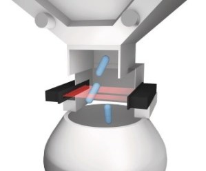
Application requirements solved by miniature optical sensors.Application requirements solved by miniature optical sensors.The requirement for miniature optical sensors to meet the demands of medical and semiconductor automation equipment often exceeds the capabilities of standard self-contained optical sensors. In some cases, other industry application requirements can be best solved by these same miniature optical sensors with advanced capabilities. So, what do these optical sensors offer that makes them so much better?

Application requirements solved by miniature optical sensors.Applications

Let’s begin with some of the applications that require these capabilities: medical applications, such as lab-on-a-chip microfluidics, liquid presence or level in drip chambers or pipettes, turbidity, drop detection, and micro or macro bubble detection, to name a few. Semicon applications include wafer presence on end-effectors, wafer mapping, wafer centering, and wafer presence in transfer chambers. Other applications that benefit from these sensors include packaging pharmaceuticals, detecting extremely small parts, and spray detection. In addition, these sensors are frequently used in customer-specific designs because they can be customized for specific applications.

Application requirements solved by miniature optical sensors.These sensors require an amplifier which sometimes is not popular with design engineers. They are associated with additional cost and extra work during installation; however, the remote amplifier offers real advantages. The optical function is separate from the control unit which allows it to be incorporated into an extremely tiny sensor head. Since the LEDs are mounted in the sensor heads, we now have a small wired connection back to the amplifier. Unlike fiber optics, this wired connection to the emitting LED and receiver allows for very minimal or no bending radius because of the cable in use.

Features

The new generation of amplifiers offers tremendous flexibility with advanced features, including:

    • OLED displayoptical sensors.
    • Intuitive menu structure
    • LEDs for status, communication, and warnings
    • Teaching/Parametrization
    • Single-point, two-point, window, dynamic, and tracking operating modes
    • Multiple teach modes: direct, dynamic, external, automatic and I/O-Link
    • Selectable power modes
    • Selectable outputsminiature optical sensors
    • Selectable speed settings
    • Auto-sync up to 8 amplifiers
    • Configurable delays and hysteresis
    • Compatible with existing all sensor heads

The sensor heads or optical heads come in a wide variety of housings, including the ability to customize them to meet specific requirements. And they are available in small precision LEDs, photodiodes, phototransistors, and complete laser modules according to a patented manufacturing process. Due to the high optical quality, additional lenses or apertures are no longer necessary.

Application requirements solved by miniature optical sensors.A multitude of special characteristics completely differentiates these sensors from the products made by standard optical sensor manufacturers. The range of products includes extraordinary miniature optical sensors as standard products, optimally adapted customized solutions, and precision optoelectronic components, such as LEDs, photodiodes, and laser modules. High optical quality, and unique modular designs, in connection with the greatest possible manufacturing flexibility, guarantee solutions that are exactly adapted to the respective problems and needs of the users.

Choosing Between M18 and Flatpack Proxes

Both M18s and flatpacks are inductive or proximity sensors that are widely used in mechanical engineering and industrial automation applications. Generally, they are similar in that they produce an electromagnetic field that reacts to a metal target when it approaches the sensor head. And the coil in both sensors is roughly the same size, so they have the same sensing range – between 5 to 8 millimeters. They also both work well in harsh environments, such as welding.

There are, however, some specific differences between the M18 and flatpack sensors that are worth consideration when setting up production.

M18

One benefit of the M18 sensor is that it’s adjustable. It has threads around it that allow you to adjust it up or down one millimeter every time you turn it 360 degrees. The M18 can take up a lot of space in a fixture, however. It has a standard length of around two inches long and, when you add a connector, it can be a problem when space is an issue.

Flatpack

A flatpack, on the other hand, has a more compact style and format while offering the same sensing range. The mounting of the flatpack provides a fixed distance so it offers less adjustability of the M18, but its small size delivers flexibility in installation and allows use in much tighter fixes and positions.

The flatpack also comes with a ceramic face and a welding cable, especially suited for harsh and demanding applications. You can also get it with a special glass composite protective face, a stainless-steel face, or a steel face with special coatings on it.

Each housing has its place, based on your detection application, of course. But having them both in your portfolio can expand your ability to solve your applications with sensor specificity.

Check out this previous blog for more information on inductive sensors and their unlimited uses in automation.

Inductive Sensors and Their Unlimited Uses in Automation

Inductive sensors (also known as proximity sensors or proxes) are the most commonly used sensors in mechanical engineering and industrial automation. When they were invented in the 1960s, they marked a milestone in the development of control systems. In a nutshell, they generate an electromagnetic field that reacts to metal targets that approach the sensor head. They even work in harsh environments and can solve versatile applications.

There are hardly any industrial machines that work without inductive sensors. So, what can be solved with one, two, three, or more of them?

What can you do with one inductive sensor?

Inductive sensors are often used to detect an end position. This could be in a machine for end-of-travel detection, but also in a hydraulic cylinder or a linear direct drive as an end-of-stroke sensor. In machine control, they detect many positions and trigger other events. Another application is speed monitoring with a tooth wheel.

What can you do with two inductive sensors?

By just adding one more sensor you can get the direction of rotational motion and take the place of a more expensive encoder. In a case where you have a start and end position, this can also be solved with a second inductive sensor.

What can you do with three inductive sensors?

In case of the tooth wheel application, the third sensor can provide a reference signal and the solution turns into a multiturn rotary encoder.

What can I do with four inductive sensors and more?

For multi-point positioning, it may make sense to switch to a measurement solution, which can also be inductive. Beyond that, an array of inductive sensors can solve identification applications: In an array of 2 by 2 sensors, there are already 16 different unique combinations of holes in a hole plate. In an array of 3 by 3, it would be 512 combinations.

Avoid Downtime in Metal Forming With Inductive & Photoelectric Sensors

Industrial sensor technology revolutionized how part placement and object detection are performed in metal forming applications. Inductive proximity sensors came into standard use in the industry in the 1960s as the first non-contact sensor that could detect ferrous and nonferrous metals. Photoelectric sensors detect objects at greater distances. Used together in a stamping environment, these sensors can decrease the possibility of missing material or incorrect placement that can result in a die crash and expensive downtime.

Inductive sensors

In an industrial die press, inductive sensors are placed on the bottom and top of the dies to detect the sheet metal for stamping. The small sensing range of inductive sensors allows operators to confirm that the sheet metal is correctly in place and aligned to ensure that the stamping process creates as little scrap as possible.

In addition, installing barrel-style proximity sensors so that their sensing face is flush with the die structure will confirm the creation of the proper shape. The sensors in place at the correct angles within the die will trigger when the die presses the sheet metal into place. The information these sensors gather within the press effectively make the process visible to operators. Inductive sensors can also detect the direction of scrap material as it is being removed and the movement of finished products.

Photoelectric sensors

Photoelectric sensors in metal forming have two main functions. The first function is part presence, such as confirming that only a single sheet of metal loads into the die, also known as double-blank detection. Doing this requires placing a distance-sensing photoelectric sensor at the entry-way to the die. By measuring the distance to the sheet metal, the sensor can detect the accidental entry of two or more sheets in the press. Running the press with multiple metal sheets can damage the die form and the sensors installed in the die, resulting in expensive downtime while repairing or replacing the damaged parts.

The second typical function of photoelectric sensors verifies the movement of the part out of the press. A photoelectric light grid in place just outside the exit of the press can confirm the movement of material out before the next sheet enters into the press. Additionally, an optical window in place where parts move out will count the parts as they drop into a dunnage bin. These automated verification steps help ensure that stamping processes can move at high speeds with high accuracy.

These examples offer a brief overview of the sensors you mostly commonly find in use in a die press. The exact sensors are specific to the presses and the processes in use by different manufacturers, and the technology the stamping industry uses is constantly changing as it advances. So, as with all industrial automation, selecting the most suitable sensor comes down to the requirements of the individual application.

IO-Link Event Data: How Sensors Tell You How They’re Doing

I have been working with IO-Link for more than 10 years, so I’ve heard lots of questions about how it works. One line of questions I hear from customers is about the operating condition of sensors. “I wish I knew when the IO-Link device loses output power,” or, “I wish my IO-Link photoelectric sensor would let me know when the lens is dirty.” The good news is that it does give you this information by sending Event Data. That’s a type of data that is usually not a focus of users, although it is available in JSON format from the REST API.

There are three types of IO-Link data:

      • Process Data – updated cyclically, it’s important to users because it contains the data for use in the running application, like I/O change of states or measurement values like temperature and position, etc.
      • Parameter Data – updated acyclically, it’s important to users because it’s the mechanism to read and write parameter values like setpoints, thresholds, and configuration settings to the sensor, and for reading non-time critical values like operating hours, etc.
      • Event Data – updated acyclically, it’s important to users because it provides immediate updates on device conditions.

Let’s dig deeper into Event Data. An Event is a status update from the IO-Link device when a condition is out of its normal range. The Event is labeled as a Warning or Error based on the severity of the condition change.

When an Event occurs on the IO-Link device, the device sets the Event Flag bit in the outgoing data packet to the IO-Link Master. The Master receives the Event Flag and then queries the IO-Link device for the Event information.

It is important to note that this is a one-time data message. The IO-Link device only sends the Event Flag at the moment the condition is out of range, and then again when the condition is back in range.

Event Data Types, Modes, and Codes

Event Data has three following three components:

      • Event Type – categorized in three ways
        • Notification – a simple event update; nothing is abnormal with the IO-Link device
        • Warning – a condition is out of range and risks damaging the IO-Link device
        • Error – a condition is out of range and is affecting the device negatively to the point that it may not function as expected
      • Event Mode – categorized in three ways
        • Event notice – usually associated with Event Type notifications, message will not be updated
        • Event appears – the condition is now out of range
        • Event disappears – the condition is now back in range
      • Event Code
        • A two-byte Hex code that represents the condition that is out of range

IO-Link condition monitoring sensor

To bring all these components together, let’s look at a photoelectric IO-Link sensor with internal condition monitoring functions and see what Events are available for it in this device manual screenshot. This device has Events for temperature (both warning and error), voltage, inclination (sensor angle is out of range), vibration, and signal quality (dirty lens).

By monitoring these events, you have a better feel for the conditions of your IO-Link device. Along with helping you identify immediate problems, this can help you in planning preventive and planned maintenance.

An IO-Link condition monitoring sensor uses Event Data similarly to report when conditions exceed the thresholds that you have set. For example, when the vibration level exceeds the threshold value, the IO-Link device sends the Warning event flag and the IO-Link Master queries for the event data. The event data consists of an Event Type, an Event Mode, and an Event Code that represents the specific alarm condition that is out of range. Remember this is a one-time action; the IO-Link sensor will not report this again until the value is in an acceptable range.

When the vibration level is back in range, the alarm condition is no longer present in the IO-Link device, the process repeats itself. In this case the Event Type and Event Code will be the same. The only change is that the Event Mode will report Event Disappears.

Within the IO-Link Specification there is a list of defined Event Codes that are common across all vendors. There is also a block of undefined Event Code values that allow vendors to create Event Codes that are unique to their specific device.

“I wish the IO-Link device would let me know….” In the end, the device might be telling you what you want to know, especially if the device has condition monitoring functions built into it. If you want to know more about condition monitoring in your IO-Link devices, check out the Event section in the vendor’s manuals so you can learn how to use this information.