

While it seems like every new trend in technology is doing away with cables, we are not yet living in a cableless working world. To get started, there are many different cabling types for use in general assembly applications. It’s important to use the right type of cable for your industrial automation application and meet any specific needs surrounding ingress protection. As I touch on this information, I’ll uncover some new ways to help you improve your assemblies and production safety and possibly, to prevent any future failures.
Common cables
Let’s start with the most common cables used in automation. Y-splitters, double-ended cordests, single-ended cordsets, and adapters are all among them and can be found in many different application environments. These cables connect PLCs, industrial networking blocks, machine vision technology, level detection sensors, traceability devices, condition monitoring solutions, and much more.
What makes each of these cables unique?
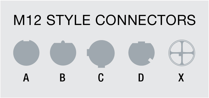
In factory automation, cable connectors come in various diameter sizes, with M12 (12mm), M8 (8mm), and 7/8” cable sizes being the most common. Also, considering the diversity in cable jackets and materials is important. Selecting the right jacket for each cable or cordset can greatly reduce the risk of field failures.
The most common cable jackets include:
-
- PVC (polyvinyl chloride): This general-purpose cable is available for use in almost every industry. While affordable, it doesn’t give your cable much protection outside of high moisture resistance.
- PUR (polyurethane): This cable offers advantages for different types of work environments. It offers good resistance from oil and ozone and is abrasion resistant, making it durable in high cable volume environments, as well as in chemical/oil plants. The only setback with this cable is its limited temperature range.
- TPE (thermoplastic): Out of the four cables listed, TPE is the most diverse when it comes to resistance. In addition to being durable and flexible, it has an excellent temperature range and is resistant to sunlight, ultraviolet radiation, and ozone. These cables are mostly found in the automotive industry but can be useful in many more.
- Silicone: Silicone cables are a great alternative if the other three options aren’t sufficient for your assembly. This cable specializes in its resistance to spark, slag, and corrosion. Silicone tubing can also be offered up to an IP69K rating, ensuring high protection. They are also commonly known for having a temperature tolerance, with a range extending up to 250 degrees Celsius. So how can you improve your automation by just changing your cables? If you’re seeing an automated weld cell failure in your assembly, it could be beneficial to look at a cable with a silicone or TPE jacket that is IP69K rated. Those harsh environments could tear through a normal PVC cable if you’re not careful.
Below is a chart that can help which cable to use in your next installation.

Cables will always play a big part in the automation process, so the next time you’re ordering a machine or sensor or doing a general inspection, make sure to choose the right cable type for your applications.


 The difference between a product being ‘explosion proof’ and ‘intrinsically safe’ can be confusing but it is vital to select the proper one for your application. Both approvals are meant to prevent a potential electrical equipment malfunction from initiating an explosion or ignition through gases that may be present in the surrounding area. This is accomplished in both cases by keeping the potential energy level below what is necessary to start ignition process in an open atmosphere.
 In all industries, there is a need for more flexible and individualized production as well as increased transparency and documentable processes. Overall equipment efficiency, zero downtime and the demand for shorter production runs have created the need for smart machines and ultimately the smart factory. Now more than ever, this is important in the Packaging, Food and Beverage (PFB) industry to ensure that the products and processes are clean, safe and efficient.


