
In industrial automation we put our products through a lot. Extreme temperatures, harsh environments, and the demands of high performance can put a strain on the components of any machine. This led me to wonder, if our products could talk, what would they say?
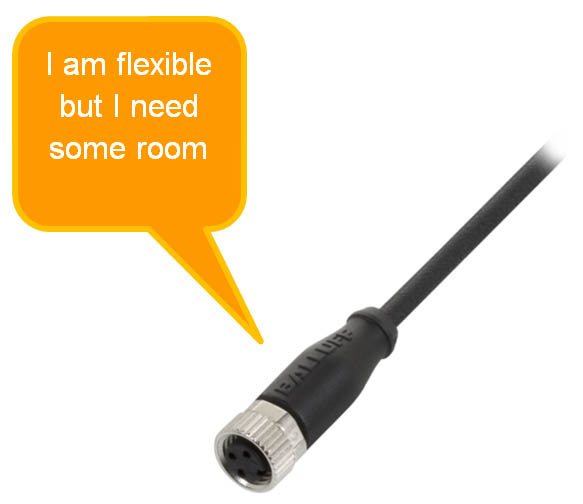 Cordset: Cables have certain limpness which makes installing the cordset in automation easier to fit in tight spaces. Most cable installers prefer to have the least amount of slack in cable to prevent the cable being snagged or pulled during operations. Cables need to have a bend radius to prevent kinking of the conductors and a continuous flow of power. The bend radius is “the smallest radius of curvature into which a material can be bent without damage” (McGraw-Hill Dictionary of Architecture and Construction). Typically in a fixed (stationary) application, an unshielded sensor cable has a minimum bending radius of 8 times the outer diameter of the cable.
 Power Supply: Everyone wants a friend. When a load is too much for one power supply, adding another power supply helps increase the voltage or current output. “The simplest method to create higher current is to connect the power supplies in parallel and leave only one supply in constant voltage mode. Some power supplies are equipped with analog control signals that allow auto-parallel or auto-tracking, a more elegant way to control multiple power supplies. Auto-parallel supplies can be controlled with a single master supply; a second advantage is that all of the master power supplies features can be used.” (Keysight Technologies) By stringing together power supplies, it allows more voltage or current but also keeps operations up and running.


