Gone are the days when an industrial camera was used only to take a picture and send it to a control PC. Machine vision systems are a much more sophisticated solution. Projects are increasingly demanding image processing, speed, size, complexity, defect recognition and so much more.
This, of course, adds to the new approach in the field of software, where deep learning and artificial intelligence play a bigger and bigger role. There is often a lot of effort behind improved image processing, however, some people, if only a few, have realized that part of it can already be processed by that little “dummy” industrial camera.
I will try to briefly explain to you in the next few paragraphs how to achieve this in your application. Thanks to that, you will be able to get some of these benefits:
- Reduce the amount of data
- Relieve the entire system
- Generate the maximum performance potential
- Simplify the hardware structure
- Reduce the installation work required
- Reduce your hardware costs
- Reduce your software costs
- Reduce your development expenses
How to achieve it?
Try to use more intelligent industrial cameras, which have a built-in internal memory sometimes called a buffer. Together with FPGA (field programmable gate array) they will do a lot of work that will appreciate your software for image processing. These functions are often also called pre-processing features.
What if you have a project where the camera must send images much faster than the USB or Ethernet interface allows?
For simple cameras, this would mean using a much faster interface, which of course would make the complete solution more expensive. Instead, you can use the Smart Framer Recall function in standard USB and GigE cameras, which generates small preview images with reduced resolution (thumbnails) with an extremely accelerated number of frames per second, which are transferred to the host PC with IDs. At the same time, the corresponding image in full resolution is archived in the camera’s image memory. If the image is required in full resolution, the application sends a request and the image is transferred in the same data stream as the preview image.
The function is explained in this video.
Is there a simpler option than a line scan camera? Yes!
Many people struggle to use line scan cameras and it is understandable. They are not easy to configurate, are hard to install, difficult to properly set and few people can modify them. You can use an area scan camera in line scan mode. The biggest benefit is standard interface: USB3 Vision and GigE Vision instead of CoaXPress and Cameralink. This enables inspection of round/rotating bodies or long/endless materials at high speed (like line scan cameras). Block scan mode acquires an Area of Interest (AOI) block which consists of several lines. The user defines the number of AOI blocks which are used to create one image. This minimizes the overhead, which you would have instead when transferring AOI blocks as single images using the USB3 Vision and GigE Vision protocols.
The function is explained in this video.
Polarization has never been easier
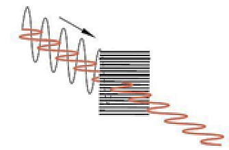
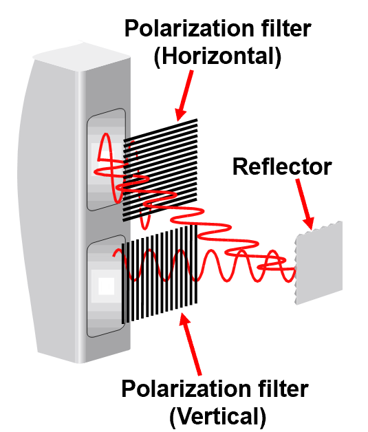
Sony came with a completely new approach to — a polarized filter . Until this new approach was developed, everyone just used a polarization filter in front of the lens and combined it with polarized lighting. With the polarized filter, above the pixel array is a polarizer array and each pixel square contains 0°, 45°, 90°, and 135° of polarization.

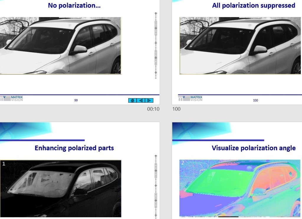
What is the best part of it? It doesn’t matter if you need a color or monochrome version. There are at least 5️ applications when you want to use it:
- Remove reflection – > multi-plane surfaces or bruise/defect detection
- Visual inspection – > detect fine scratches or dust
- Contrast improvement -> recognize similar objects or colors
- 3D/Stress recognition -> quality analysis
- People/vehicle detection -> using your phone while driving
Liquid lens is very popular in smart sensor technology. When and why do you want to use it with an Industrial camera?

Liquid lens is a single optical element like a traditional lens made from glass. However, it also includes a cable to control the focal length. In addition, it contains a sealed cell with water and oil inside. The technology uses an electrowetting process to achieve superior autofocus capabilities.
Benefits to the traditional lenses are obvious. It doesn’t have any moving mechanical parts. Thanks to that, they are highly resistant to shocks and vibrations. Liquid lens is a perfect fit for applications where you need to observe or inspect objects with different sizes and/or working distances and you need to react very quickly. One liquid lens can do the work of multiple-image systems.
To connect the liquid lens, it requires the RS232 port in the camera plus a DC power from 5 to 24 Volt. An intelligent industrial camera is able to connect with the camera directly and the lens uses the power supply of the camera.