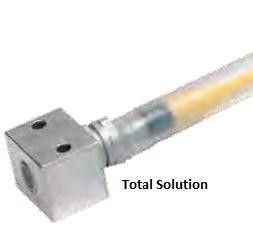
Protect Your Sensors – Implement the 3-Step Process

When installing sensors into a harsh environment, for example a weld cell application, protecting the sensor is a crucial step in the installation process.  These sensors are exposed to extreme heat, weld slag and sometimes impact.  In order to reduce sensor usage, the sensor needs to be protected from the harsh area of exposure.  This can be achieved by using a complete sensor protection method that includes proper sensor selection such as sensors that have a weld slag resistant coating, proper mounting and cable protection.  If you follow these steps the end result will be longer sensor life.

  • Step 1
    • Identify form factor (size of sensor)
    • Output polarity (DC 3wire PNP, NPN etc.)
    • Identify special sensor characteristics (Slag resistant coating, SteelFace, F1 etc.)
  • Step 2
    • Select your mechanical protection system (ProxMount etc.)
  • Step 3
    • TPE cable
    • WeldRepel tubing and wrap

So, by simply implementing the three step total solution into your harsh or extreme application you can protect and lengthen the life of the sensors and cables providing less downtime. For more information on the total solution, check out this whitepaper on Increasing Sensor Life and Production Productivity.

Protect your sensors

Total Solution

Inductive Sensor Correction Factor

Some applications have multiple materials that have to be detected. When specifying a standard inductive proximity sensor the first question asked is, “what is the target material that will need to be detected.” In my previous post, I indicated that the ideal target for an inductive sensor is a target made from mild steel. This is correct; however, an inductive sensor can also detect non-ferrous materials but a correction factor has to be determined into the rated operating distance of your selected sensor. For example, if you select a sensor that has 4mm of operating distance (Rated Operating Distance), and the target is aluminum, we would multiply a correction factor of 0.30-0.45 to get the new rated operating distance of your sensor (1.2mm -1.8mm). Due to the aluminum’s non-ferrous material we can no longer achieve the 4mm rated operating distance in proximity to the aluminum target.

Continue reading “Inductive Sensor Correction Factor”

When Do You Specify An Inductive Sensor?

Many times when you look at an application you ask yourself, what is the best type of   sensor for my application? Let’s assume that we have an application that calls for a metal target. In this case an Inductive Sensor is going to be our first choice if the operating range is relatively short (Typically less than two inches). Inductive sensors are great for applications that require a rugged sensor that can withstand vibration.

Main Applications for Inductive Sensors

  • Machine Position Verification…
    • Are the machine components in the proper position?
  • Part Position Verification…
    • Is the part itself in the correct location?
  • Part Feature Verification…
    • Did a process happen that should have?

Continue reading “When Do You Specify An Inductive Sensor?”

Back to the Basics – How do I wire my 3-wire sensors?

Three-wire sensors are used in various applications from detecting parts to locating position of the actual machine. They can come in all different technologies such as inductive sensors, photoelectric sensors and capacitive sensors, just to list a few. Although the sensor technology may differ, all 3-wire sensors are wired the same way.

A three-wire sensor has 3 wires present: two power wires and one load wire. The power wires will connect to a power supply and the remaining wire to some type of load. The load is a device that is being controlled by the sensor. The most common type of load would be a PLC (programmable logic controller) DC input. Other examples of a load could be a relay or machine alarm. Just make sure the load rating of the sensor is not exceeded. A typical 3-wire DC sensor’s output has a rating of 100mA to 200mA.

As an example, let’s reference an inductive proximity sensor. When a target (the object that a sensor is detecting) comes within sensing range of the sensor, the sensor output turns on and current flows. A 3-wire sensor typically is color coded with one brown wire, one blue wire and one black wire. The brown wire is the +VDC wire that connects to the positive (+) side of the power supply and the blue wire is connected to the common terminal of the power supply — this is the negative (-) terminal that is present on the power supply. The black wire is the output (load) wire of the sensor. 3-wire DC sensors can have a PNP (sourcing) or NPN (sinking) output. Just make sure the correct sensor part number is selected for the correct transistor circuit.

There you have it! As you can see wiring a 3-wire sensor is not too difficult.

PNP N/O
PNP N/C
NPN N/O
NPN N/C

Inductive Proximity Sensor Targets – Material does matter

Written by: Jeff Himes

From some of the previous blogs, it has been indicated that a number of variables can affect the actual sensing range achieved by an inductive proximity sensor.  One of those variables mentioned was target composition or target material.  Let’s review how various target materials can affect an inductive sensor’s performance.

Continue reading “Inductive Proximity Sensor Targets – Material does matter”