Automation Insights: Top 10 Blogs From 2023

In 2023, the industrial automation sector experienced significant advancements and transformative trends, shaping the landscape of manufacturing and production processes. Listed below are our top 10 blogs highlighting some of these advancements, from streamlined changeover processes using RFID to machine safety levels determined through risk assessments and a proactive approach to unplanned downtime using condition monitoring. Other blogs explored UHF RFID considerations, communication protocol analysis, camera selection guidance for engineers, machine safety practices emphasis, and discussions on IO-Link and MQTT benefits for automation projects.

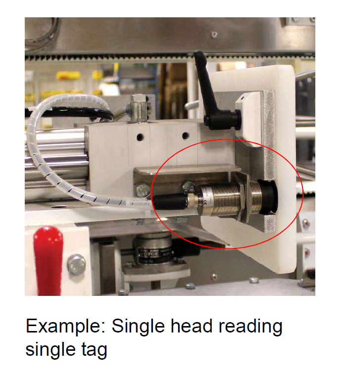
    1. Using RFID Technology for Rapid Changeover

In today’s tight economy, marked by high inflation and supply chain issues, the need to enhance product flexibility has become increasingly important. Most manufacturing lines these days are set up to run multiple work orders of the same product type based on specific requirements. The goods produced at the manufacturer line are still the same, but the package size can change. The raw materials that start the process might be the same, but other component parts and tools on the machine that help with the different packaging sizes must be replaced. The process of converting one product line or machine to another is known as changeover. This blog explores how Radio Frequency Identification (RFID) technology can revolutionize changeover by eliminating manual verification and adjustments.

Read more.

    1. Understanding Machine Safety: The Power of Risk Assessments

My last blog post was about machine safety with a focus on the different categories and performance levels of machine safety circuits. But I just briefly touched on how to determine these levels. By default, we could design all equipment with the highest-level category and performance levels of safety with an abundance of caution, but this approach could be extremely expensive and not the most efficient.

Read more.

    1. Getting Started With Condition Monitoring

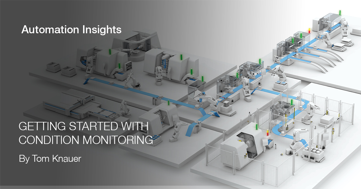
Unplanned downtime is consistently identified as one of the top manufacturing issues. Condition monitoring can offer a fairly simple way to start addressing this issue and helps users become more proactive in addressing and preventing impending failures of critical equipment by using data to anticipate problems.

Read more.

    1. Sensing Ferrous and Non-Ferrous Metals: Enhancing Material Differentiation

Detecting metallic (ferrous) objects is a common application in many industries, including manufacturing, automotive, and aerospace. Inductive sensors are a popular choice for detecting metallic objects because they are reliable, durable, and cost-effective. Detecting a metallic object, however, is not always as simple as it seems, especially if you need to differentiate between two metallic objects. In such cases, it is crucial to understand the properties of the metals you are trying to detect, including whether they are ferrous or non-ferrous.

Read more.

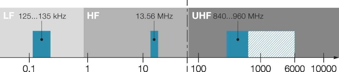
    1. Considerations When Picking UHF RFID

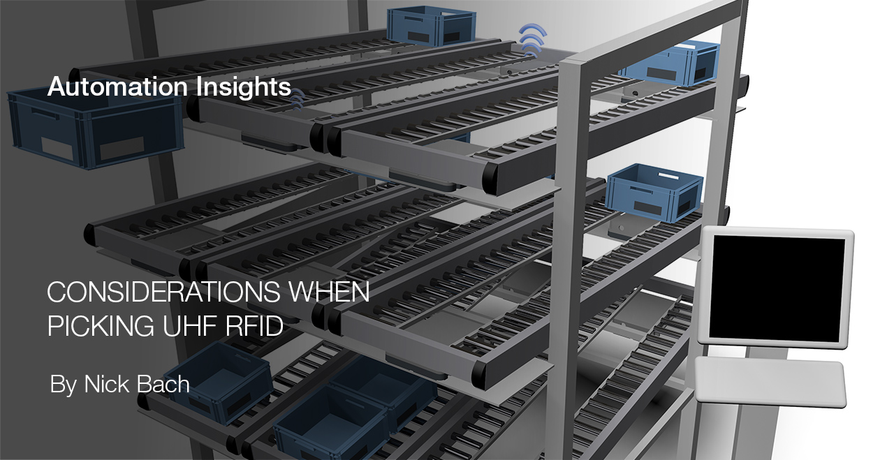
If you’ve attempted to implement an ultra-high frequency (UHF) RFID system into your facility, you might have run into some headaches in the process of getting things to work properly. If you are looking to implement UHF RFID, but haven’t had the chance to set things up yet, then this blog might be beneficial to keep in mind during the process.

Read more.

    1. Comparing IO-Link and Modbus Protocols in Industrial Automation

In the realm of industrial automation, the seamless exchange of data between sensors, actuators, and control systems is critical for optimizing performance, increasing efficiency, and enabling advanced functionalities. Two widely used communication protocols, IO-Link and Modbus, have emerged to facilitate this data exchange. In this blog, I’ll analyze the characteristics, strengths, and weaknesses of both protocols to help you choose the right communication standard for your industrial application.

Read more.

    1. Exploring Industrial Cameras: A Guide for Engineers in Life Sciences, Semiconductors, and Automotive Fields 

In the bustling landscape of industrial camera offerings, discerning the parameters that genuinely define a camera’s worth can be a daunting task. This article serves as a compass, steering you through six fundamental properties that should illuminate your path when selecting an industrial camera. While the first three aspects play a pivotal role in aligning with your camera needs, the latter three hold significance if your requirements lean towards unique settings, external conditions, or challenging light environments.

Read more.

    1. Focusing on Machine Safety

Machine safety refers to the measures taken to ensure the safety of operators, workers, and other individuals who may encounter or work in the vicinity of machinery. Safety categories and performance levels are two important concepts to evaluate and design safety systems for machines. A risk assessment is a process to identify, evaluate, and prioritize potential hazards and risks associated with a particular activity, process, or system. The goal of a risk assessment is to identify potential hazards and risks and to take steps to prevent or mitigate those risks. The hierarchy of controls can determine the best way to mitigate or eliminate risk. We can use this hierarchy, including elimination, substitution, engineering, and administrative controls, and personal protective equipment (PPE), to properly mitigate risk. Our focus here is on engineering controls and how they relate to categories and performance levels.

Read more.

    1. Why Choose an IO-Link Ecosystem for Your Next Automation Project?

By now we’ve all heard of IO-Link, the device-level communication protocol that seems magical. Often referred to as the “USB of industrial automation,” IO-Link is a universal, open, and bi-directional communication technology that enables plug-and-play device replacement, dynamic device configuration, centralized device management, remote parameter setting, device level diagnostics, and uses existing sensor cabling as part of the IEC standard accepted worldwide.

Read more.

    1. Using MQTT Protocol for Smarter Automation

In my previous blog post, “Edge Gateways to Support Real-Time Condition Monitoring Data,” I talked about the importance of using an edge gateway to gather the IoT data from sensors in parallel with a PLC. This was because of the large data load and the need to avoid interfering with the existing machine communications. In this post, I want to delve deeper into the topic and explain the process of implementing an edge gateway.

Read more.

We appreciate your dedication to Automation Insights in 2023 and look forward to growth and innovation in 2024.

Know Your RFID Frequency Basics

In 2008, I purchased my first toll road RFID transponder, letting me drive through and pay my toll without stopping at a booth. This was my first real-life exposure to RFID, and it was magical. Back then, all I knew was that RFID stood for “radio frequency identification” and that it exchanged data between a transmitter and receiver using radio waves. That’s enough for a highway driver, but you’ll need more information to use RFID in an industrial automation setting. So here are some basics on what makes up an RFID system and the uses of different radio frequencies.

At a minimum, an RFID system comprises a tag, an antenna, and a processor. Tags, also known as data carriers, can be active or passive. Active tags have a built-in power source, and passive tags are powered by the electromagnetic field emitted by the antenna and are dormant otherwise. Active tags have a much longer range than passive tags. But passive tags are most commonly used in industrial RFID applications due to lower component costs and no maintenance requirements.

Low frequency (LF), high frequency (HF), ultra-high frequency (UHF)

The next big topic is the different frequency ranges used by RFID: low frequency (LF), high frequency (HF), and ultra-high frequency (UHF). What do they mean? LF systems operate at a frequency range of 125…135 kHz, HF systems operate at 13.56 MHz, and UHF systems operate at a frequency range of 840…960 MHz. This tells you that the systems are not compatible with each other and that you must choose the tag, antenna, and processor unit from a single system for it to work properly. This also means that the LF, HF, and UHF systems will not interfere with each other, so you can install different types of RFID systems in a plant without running a risk of interference or crosstalk issues between them or any other radio communications technology.


Choosing the correct system frequency?

How do you choose the correct system frequency? The main difference between LF/HF systems and UHF systems is the coupling between the tags and the antenna/processor. LF and HF RFID systems use inductive coupling, where an inductive coil on the antenna head is energized to generate an inductive field. When a tag is present in that inductive field, it will be energized and begin communications back and forth. Using the specifications of the tag and the antenna/processor, it is easy to determine the read/write range or the air gap between the tag and the antenna head.

The downside of using LF/HF RFID technology based on inductive coupling is that the read/write range is relatively short, and it’s dependent on the physical size of the coils in the antenna head and the tag. The bigger the antenna and tag combination, the greater the read/write distance or the air gap between the antenna and the tag. The best LF and HF RFID uses are in close-range part tracking and production control where you need to read/write data to a single tag at a time.

UHF RFID systems use electromagnetic wave coupling to transmit power and data over radio waves between the antenna and the tag. The Federal Communications Commission strictly regulates the power level and frequency range of the radio waves, and there are different frequency range specifications depending on the country or region where the UHF RFID system is being used. In the United States, the frequency is limited to a range between 902 and 928MHz. Europe, China, and Japan have different operating range specifications based on their regulations, so you must select the correct frequency range based on the system’s location.

Using radio waves enables UHF RFID systems to achieve a much greater read/write range than inductive coupling-based RFID systems. UHF RFID read/write distance range varies based on transmission power, environmental interference, and the size of the UHF RFID tag, but can be as large as 6 meters or 20 feet. Environmental interferences such as metal structures or liquids, including human bodies, can deflect or absorb radio waves and significantly impact the performance and reliability of a UHF RFID system. UHF RFID systems are great at detecting multiple tags at greater distances, making them well suited for traceability and intralogistics applications. They are not well suited for single tag detection applications, especially if surrounded by metal structures.

Because of the impact an environment has on UHF signals, it is advisable to conduct a full feasibility study by the vendor of the UHF RFID system before the system solution is purchased to ensure that the system will meet the application requirements. This includes bringing in the equipment needed, such as tags, antennas, processors, and mounting brackets to the point of use to ensure reliable transmission of data between the tag and the antenna and testing the system performance in normal working conditions. Performing a feasibility study reduces the risk of the system not meeting the customer’s expectations or application requirements.

Selecting an industrial RFID system

There are other factors to consider when selecting an industrial RFID system, but this summary is a good place to start:

    • Most industrial RFID applications use passive RFID tags due to their lower component costs and no battery replacement needs.
    • For applications requiring short distance and single tag detection, LF or HF RFID systems are recommended.
    • For applications where long-distance and multi-tag detection is needed, UHF RFID systems are recommended.
    • If you are considering UHF, a feasibility study is highly recommended to ensure that the UHF RFID system will perform as intended and meet your requirements.

Click here to browse our library of Automation Insights blogs related to RFID.

UHF RFID Versus UHF RTLS

Many companies new to UHF (Ultra High Frequency) RFID (Radio Frequency Identification) confuse it with UHF RTLS (Real Time Location Systems). While both indeed do use UHF RFID, they differ substantially in what they can actually do for you in your business.

Many companies new to UHF (Ultra High Frequency) RFID (Radio Frequency Identification) confuse it with UHF RTLS (Real Time Location Systems). While both indeed do use UHF RFID, they differ substantially in what they can actually do for you in your business.
UHF RFID

Standard UHF RFID systems can see multiple tags on equipment and products up to several meters away, if set up properly. With emphasis on “set up properly.” While UHF RFID works quite well, its unique characteristics require testing in the environment where it will be used to ensure success.

UHF RFID has several purposes:

    • To see if an item has passed a certain point, commonly known as a choke point. Examples of this are items being loaded on or off a trailer at a shipping door or items passing from one area to another in a plant.
    • To verify if something is within a certain area when using a scanning device, such as a handheld reader. If one is scanning shelves of parts or equipment, it will help locate those items.
    • To track usage of equipment in MIS systems.
    • The tags can also have data written to them if needed.

The big thing that UHF RFID cannot do is effectively track the exact location of something at any given time in a cost-effective manner. Generally, UHF RFID uses what are called passive tags for the antennas to read. These tags have no battery and get energized from the antenna signal. If you placed enough antennas all over a facility and enough of these tags, then you could possibly locate something within a certain proximity, but not exactly, and this is hardly cost effective.

UHF Real Time Location Systems (RTLSs)

RTLS, on the other hand, are specifically designed to pinpoint the location of anything with a tag or transponder on it. In fact, RTLS refers to any system that can accurately determine an item or person’s location. An important aspect of RTLS is how frequently assets must be tracked. This data can be used in different ways depending on the application. For example, some RTLS applications only need timestamps when an asset passes through an area, while others require much higher visibility, requiring constant updating of time data.

An ideal RTLS can accurately locate, track, and manage assets, inventory, or people, and help companies make knowledgeable decisions based on collected location data.

Like regular UHF RFID, RTLS can use passive or active tags (tags with batteries), but they use triangulation of multiple antennas to determine the location of an object or person. The strength of the signal at each antenna, combined with the software attached to the antennas, allows the identification of the location of an object or person within less than 1 meter.

The system you choose depends on the needs at your location. They both work quite well when implemented properly by trained professionals.

Also, due to the inherent properties of ultra-high frequencies used in UHF RFID technology and RTLS, you should perform a feasibility study that actually tests the system in the real world environment of the plant prior to implementing these systems in any application.

UHF RFID: Driving Efficiency in Automotive Production

Manufactured in batch size 1, bumper to bumper on modular production lines, with the support of collaborative robots –  this is the reality in modern automotive production. Without transparent and continuous processes, production would come to a standstill. Therefore, it is important to have reliable technology in use. For many car manufacturers, UHF RFID is not only used to control manufacturing within a plant but recently more and more also to track new vehicles in the finishing and even shipping processes. And many manufacturers have already started using UHF across production plants and even across companies with their suppliers because it makes just-in-time and just-in-sequence production a lot easier. This blog post gives an insight into why UHF could be the technology of the future for automotive production.

What is UHF?

UHF stands for ultra-high frequency and is the frequency band of RFID (Radio Frequency Identification) from 300 MHz to 3 GHz. UHF with the EPC global Gen2 UHF standard typically in the frequency range of 860 – 960 MHz, with regional differences. Besides UHF other popular RFID frequency bands used in production are LF (low frequency) – operating typically at 125 kHz – and HF (high frequency) – operating typically at 13.56 MHz worldwide. LF is used mainly for Tool ID and HF for ticketing, payment, and production and access control.

UHF RFID used to ensure the proper headrest is placed on automotive seats.
An RFID sensor scans a tag on a car headset during production

UHF systems have the longest read range with up to a few meters and a faster data transfer rate than LF or HF. Therefore, it’s used in a wide variety of applications and the fastest growing segment of the RFID market. Tracking goods or car parts in the supply chain, inventorying assets, and authenticating car parts are just some examples for the automotive industry.

And this is how it works: A UHF reader emits a signal and energy to its environment via an antenna. If a UHF data carrier can be activated by this energy, a data exchange can take place. The data carrier or tag backscatters the reader signal and modulates it according to its specific data content.

UHF vs. Optical systems

Intelligent data generated by intelligent RFID solutions is a crucial part of efficient and transparent processes. To achieve this, the use of innovative UHF technology is essential. Because in the long-term UHF could replace existing HF or LF RFID applications as well as optical systems. Due to its wider range of functions and performance, UHF has the potential to enable a cross-enterprise data flow.

This table shows that UHF can offer a performance and interaction that optical formats can’t:


  UHF Systems Optical Systems
Automation Automated process reduces or eliminates manual scanning Manual scanning or low-level automation
Speed 20,000 units per hour (ms/read) 450 units per hour (s/read)
Convenience Can scan items even when they are hidden from view or inside a package Can scan only what it can see
Efficiency Scanning many at once is possible Scans one at a time
Intelligence Chip memory, which can be updated or rewritten to create a more dynamic and responsive process Static data on the label
Security Security features, such as authentication, can be offered on the item level Security features not available or even possible

Sometimes short range is required

Although the UHF technology can read up to a few meters – which is perfect and even required for (intra)logistic processes – this can also be a challenge, especially in some manufacturing areas. Within part production it is often necessary that the detection range is limited and only one part is detected at a time. In these cases, it’s important that the power is either turned down so far that only one part is detected at a time or a special short-range UHF reader resp. special short-range antenna are used.

The technology’s potential can only be fully exploited if every stage of production is supported by UHF. The use of UHF is versatile and can either be used as closed-loop where the UHF tag stays in the production process or as open-loop with UHF labels that are glued onto or into parts like car bodies, bumpers, head rests, tires etc. where they will remain and possibly be used during the subsequent logistics applications.

Besides eliminating manual processes, UHF RFID delivers full visibility of your inventory (automated!) at any time which helps you to reduce shrinkage and prevent stock losses. This improves your overall business operations. Additionally, you can secure access to certain areas.

Another reason to rely up on UHF is the consistently high standard of data quality. When you acquire the same data type from all areas you can generate trend analysis as the readings can be compared with one another. So, you can obtain extensive information on the entire production process – something that isn’t possible when mixing different technologies. This gives you the opportunity to utilize preventive measures.


Which RFID Technology is Best for Your Traceability Application?

There are a lot of articles on using RFID for traceability, but it’s hard to know where to begin. Examples of traceability include locating an important asset like a specific mold that is required to run a machine or verifying a specific bin of material required to run production. Spending time looking for these important assets leads to lost time and production delays. RFID can help but understanding the different RFID capabilities will narrow down the type of RFID that is required.

Not all RFID technology is the same. Each RFID technology operates differently and is categorized by the frequency band of the radio spectrum, such as low frequency, high frequency and ultra-high frequency. In low and high frequency RFID, the read range between RFID tag and reader antenna is measured in millimeters and inches. The read range on ultra-high frequency (UHF) RFID technology can range from one meter to 100 meters. Typically, inventory traceability is done using ultra-high frequency band of the radio frequency spectrum, due to the need to read the asset at a further distance so it does not interfere with the production flow. Also, there are cases where there needs to be a reading of multiple tags in an area at the same time to determine where an asset is located. UHF RFID technology allows for simultaneous reading of multiple RFID tags from a single antenna reader.

There are two types of UHF RFID, passive and active.  Passive UHF RFID means that the RFID tags themselves have no additional power source. The UHF reader antenna sends out an electromagnetic wave field, and the RFID tags within the electromagnetic field have an internal antenna that receives the energy which activates the integrated circuit inside the tag to reflect the signals back to start communicating. The read distance between the passive RFID tag and antenna reader is determined by several factors, such as the size of the electromagnetic wave field generated out of the reader antenna and the size of the receiver antenna on the RFID tag. Typical read ranges on passive UHF systems can be anywhere from one to 12 meters, where the larger the power and RFID tag, the longer the range.

Active UHF RFID systems do not require the tag to reflect signals back to communicate because the active RFID tag has its own transmitter and internal battery source. Because of this, with active UFH RFID you can get read ranges of up to 100 meters. There are active tags which wake up and communicate when they receive a radio signal from a reader antenna, while others are beacons which emit a signal at a pre-set interval. Beacon active tags can locate in real time the location of the asset that the RFID tag is attached to. However, a downfall to active RFID tags is the battery life on the tag. If the battery is dead, then the asset will no longer be visible.

Figure 1

Once the strengths and weaknesses of each type of UHF RFID system is known, it’s easier to work with the constraints of the system. For example, the application in Figure 1 shows a reader antenna for reading bins of material placed a few feet away so that its’ not in the way of production. A passive UHF RFID system will work in this case, due to the distance between the antenna and the RFID tag on the bin a few feet away. There is no need to worry about battery life on the passive RFID tag.

Figure 2

If the exact location of a production mold is required in a large facility, then using an active UHF RFID system is likely a better fit. Incorporating an active RFID tag that sends out a beacon at a fixed interval to a data center ensures the location of all assets are always known. With this setup, the exact location of the mold can be found at any time in the facility.

Examining the different types of RFID technology can help determine the correct one to use in a traceability application. This includes analyzing the pros and cons of each technology and seeing which one is the best fit for the application.

Using Long-Range RFID for Metal Stamping Die Identification

Using incorrect dies for metal stamping operations can result in lost time and production as well as severe damage to the presses and a risk to human lives.

In recent years, there was a case where the use of the incorrect die caused catastrophic press damage resulting in significant downtime and, because the press was so large, it had to be cut up before it could be removed and replaced. These types of occurrences can prove disastrous to the survival of a company.

When not in use, dies are generally stored in specified storage areas. Often, the die is in the wrong place, and the crane operator needs to know what he/she is retrieving for the next process in the correct die.

To help ensure that these types of errors do not occur, some manufacturers use long-range UHF RFID technology. This can ensure that the correct dies are chosen when they are staged outside of a press. And with handheld devices, it can help the operator find the correct die in storage if it has been misplaced.

Since long-range UHF RFID technology allows the verification of the correct dies from as little as one foot away to as far as several meters, it can be used in both large and small stamping presses. The long-range allows the reader antennas to be placed in strategic locations where the correct readings will be possible but in positions where they will not be damaged by the operation of the press and dies.

I recently assisted with a metal stamping operation that first brought this idea to my attention. This manufacturer was having the problem of the wrong dies being staged for installation into the press. So far, none of the dies had made it past the staging area and into the press. Still, the possibility of that happening was clearly present, and they were experiencing lost production due to having to remove the incorrect die and find the correct one.

The manufacturer wanted to interlock the press so that if the incorrect dies were not in place, the machine would not be able to run. He also wanted to know ahead of time of a wrong die so that it could be replaced promptly to not impact production.

The solution we developed was to place multiple reader antennas at multiple staging locations at the press and interlock the RFID reads with the PLC that controlled the press.

Additionally, he incorporated handheld readers to help find misplaced dies in the storage area.

This solution required testing and tuning of the UHF RFID system to ensure that all die RFID tags were being read when the dies were staged. But once this was completed, it proved to work effectively and reduce the errors and downtime.

It should be noted that due to the physics of UHF RFID technology versus other types of RFID technology, implementing long-range UHF RFID systems in any application should be preceded by a feasibility study that tests the system in the real world environment of the plant.

RFID Minimizes Errors, Downtime During Format Change

Today’s consumer packaged goods (CPG) market is driving the need for greater agility and flexibility in packaging machinery. Shorter, more customized runs create more frequent machine changeover. Consequently, reducing planned and unplanned downtime at changeover is one of the key challenges CPG companies are working to improve.

In an earlier post, I discussed operator guided changeover for reducing time and errors associated with parts that must be repositioned during format change.

In this post, I will discuss how machine builders and end users are realizing the benefits of automated identification and validation of mechanical change parts.

In certain machines, there are parts that must be changed as part of a format change procedure. For example, cartoning machines could have 20-30 change parts that must be removed and replaced during this procedure.

This can be a time consuming and error-prone process. Operators can forget to change a part or install the wrong part, which causes downtime during the startup process while the error is located and corrected. In the worst scenarios, machines can crash if incorrect parts are left in the machine causing machine damage and significant additional downtime.

To prevent these mistakes, CPG companies have embraced RFID as a way to identify change parts and validate that the correct parts have been installed in the machine prior to startup. By doing so, these companies have reduced downtime that can be caused by mistakes. It has also helped them train new operators on changeover procedures as the risk of making a mistake is significantly reduced.

Selecting the correct system

When looking to add RFID for change part validation, the number of change parts that need to be identified and validated is a key consideration. RFID operating on the 13.56 MHz (HF) frequency has proven to be very reliable in these applications. The read range between a read head and tag is virtually guaranteed in a proper installation. However, a read head can read only a single tag, so an installation could need a high number of read heads on a machine with a lot of change parts.

1

It is also possible to use the 900 MHz (UHF) frequency for change part ID. This allows a single head to read multiple tags at once. This can be more challenging to implement, as UHF is more susceptible to environmental factors when determining read range and guaranteeing consistent readability. With testing and planning, UHF has been successfully and reliably implemented on packaging machines.

2

Available mounting space and environmental conditions should also be taken into consideration when selecting the correct devices. RFID readers and tags with enhanced IP ratings are available for washdown harsh environmental conditions. Additionally, there are a wide range of RFID read head and tag form factors and sizes to accommodate different sized machines and change parts.


Manufacturers Track Goods, Reduce Errors, Decrease Workload with RFID

More and more, retailer sellers are starting to require that manufacturers place RFID tags on their products before they leave the production facility and are shipped to those retail locations. From high-end electronics all the way down to socks and underwear are being tagged.

These tags are normally supplied by the retailer or through a contracted third party. Typically disposable UHF paper tags, they are only printed with a TID number and a unique EPC that may or may not correspond to the UPC and barcode that was used in the past. Most cases I have seen require that the UPC and a barcode be printed on these RFID tags so there is information available to the human eye and a barcode scanner when used.

While this is being asked for by the retailers, manufacturers can use these tags to their own advantage to track what products are going out to their shipping departments and in what quantities. This eliminates human error in the tracking process, something that has been a problem in the past, while also reducing workload as boxes of finished goods no longer must be opened, counted and inspected for accuracy.

A well-designed RFID portal for these items to pass through can scan for quantities and variances in types of items in boxes as they pass through the portal. Boxes that do not pass the scan criteria are then directed off to another area for rework and reevaluation. Using human inspection for just the boxes that do not pass the RFID scan greatly reduces the labor effort and expedites the shipping process.

I recently assisted with a manufacturer in the garment industry who was having to tag his garments for a major retailer with RFID tags that had the UPC and a barcode printed on them. The tags were supplied through the retailer and the EPCs on the tags were quite different then the UPC numbers printed on them.

The manufacturer wanted to know how many garments of each type were in each box. Testing showed that this could be done by creating a check point on his conveyor system and placing UHF RFID antennas in appropriate locations to ensure that all the garments in the box were detected and identified.

In this case, the manufacturer wanted was a simple stand-alone system that would display a count of different types of garments. An operator reviewed the results on a display and decided based on the results whether to accept the box and let the conveyor forward it to shipping or reject it and divert it to another conveyor line for inspection and adjustment.

While this system proved to be relatively simple and inexpensive, it satisfied the desires of the manufacturer. It is, however, possible to connect an RFID inspection station to a manufacturing information system that would know what to expect in each box and could automatically accept or reject boxes based on the results of the scans without human intervention and/or human error.

Traceability of production material with RFID

As we progress toward a more automated factory, the need to more efficiently manage what happens prior to the production process has become apparent. Tracking of raw material and production components from the dock door to the warehouse is quickly evolving from a best guess estimate to real-time inventory levels driven by production. Essentially, we are moving from a practice of holding just-in-case inventory to Just-in-Time (JIT) inventory. The JIT concept helps to optimize the amount of in-house inventory based on production. In addition, the entire supply chain benefits because the levels of raw goods inventory upstream can be managed more efficiently and forecasted with more accuracy.

RFID and barcode technology have played a critical role in the actual production process for decades, but its benefits are currently being leveraged in other areas of the plant as well. Whether its tracking every item or every pallet that comes into the receiving dock, ID traceability provides visibility where it did not exist before.

Traceability of production material 

Upon receiving a pallet with raw material, the 2D matrix code on the shipping label is read by a barcode scanner. The relevant data needed for the further traceability process is transferred onto the stack of trays which contain UHF carriers. The number of carriers is saved together with the traceability data in a database. This process takes place at one single station and the data is updated immediately to represent the inventory level.

Transmission of incoming goods data on the transponder

Automated review of loaded pallets

Based on the material number, the system contains a standard load for the number of trays on the pallet. An automatic screening takes place to determine if all transponders on the pallet are registered. In case of a difference between the registered data and the expected data, an error message pops up to indicate the need for manual intervention. This process allows for proactive management of inventory to prevent false inventory levels or goods that cannot be accounted for.

Key Features of a traceability solution:

  • Corresponds to the global ISO standard
  • Suitable for attachment to major control systems via bus interfaces and higher level IT systems
  • Variety of accessories available for easy integration into different applications

To learn more about RFID technology, visit www.balluff.com.

How RFID Can Push Your Automotive Production Into the Fast Lane

The automotive industry is one of the technological trendsetters in the manufacturing industry. In 1913 Henry Ford invented the assembly line and forever changed automotive production. Now a bit more than a century later the automotive industry is again facing one the biggest innovations in its history.

The complexity of different models and the variety of equipment variations are enormous. This individuality comes with great challenges. The workers in the assembly process are confronted with countless, almost identical components. This requires accurate tracking of all items to avoid mistakes. Safety-relevant components are, therefore, often provided with a barcode that has to be scanned manually.

The major advantages of RFID over barcodes in automotive production

Another technology could relieve employees of this routine task and give them the security of having installed the right parts through automatic testing: RFID. These are the big advantages of RFID over barcodes:

  • While the barcode only contains the information about which type of product it is, the RFID tag provides additional information, such as in which vehicle the car seat is to be installed.
  • While the barcodes have to be read out manually one after the other with a handheld scanner, the RFID tags can all be detected simultaneously and without contact via a scanner – even if the parts are already installed.
  • RFID tags can be used to retrieve information in seconds at any time. During the production process, it can already be checked whether all the required components are installed –  provided they are all equipped with an RFID tag. Without RFID, this was only recorded in the final inspection, using visual inspection and paper list.
  • Additionally, nowadays it is indispensable for the automotive industry to make the production parts traceable and thereby assign them a unique identity. RFID has the advantage that without visual contact or even after a repainting of the component, the information can be easily retrieved. The function is not lost with dirt or oil coverage. Furthermore, tags with special encapsulation can retain their function even under high mechanical, thermal or chemical loads.

How does RFID work?

RFID is the identification of objects by electromagnetic waves.  A reader generates a high-frequency electromagnetic field. If a data carrier (also called “tag”) is brought into the vicinity of the reader, the specific structure of the tag ensures a change in the field and thus transmits individual information about itself – contactless.

RFID Tag and Reader
Functional principle of an RFID system

Increase process reliability and profitability with RFID

Several thousand parts are needed to build a car. But only those parts that are safety, environmentally or testing relevant get an RFID tag. For example, the motor cabling would get a tag that can be read out automatically. Without RFID a worker would have to manually enter the label in a database and errors can easily arise. RFID detects the part automatically and you don’t have to look for labels in transport boxes, etc.

With RFID you know exactly where a component is located at any time – from the moment of delivery until the belt run of the car. With this information you can react flexibly to changes in the process, such as delays in certain areas, and can reschedule at short notice. In addition, you can always retrieve the current stock and know whether the right component is mounted on the right vehicle. So it can significantly increase process reliability and efficiency. An RFID solution eliminates several manual steps in the documentation per vehicle, and it brings more transparency to the logistics and production processes. That means the effort is reduced and the profitability increases.

The implementation starts with the suppliers

Ideally, the implementation of RFID starts with the automotive suppliers. They attach the RFID tags to their components what allows them to use the technology within their own logistics and manufacturing facilities. On arrival to the car manufacturer, the parts are driven through an RFID gate that reads out the tags automatically and adds the parts to the inventory. If the car leaves the assembly hall after manufacturing you can screen again by the RFID gate. At the push of a button it can show which parts are under the hood.

Automatic configuration with UHF for your convenience

The processes in the automotive industry are versatile, but a broad selection of innovative RFID products can push your automotive production into the fast lane.

For more information on RFID, visit www.balluff.com.