Basic Sensors for Robot Grippers

Robot gripper with inductive proximity sensors mounted

Typically when we talk about end-of-arm tooling we are discussing how to make robot grippers smarter and more efficient. We addressed this topic in a previous blog post, 5 Tips on Making End-of-Arm Tooling Smarter. In this post, though, we are going to get back to the basics and talk about two options for robot grippers: magnetic field sensors, and inductive proximity sensors.

One of the basic differences is that detection method that each solution utilizes. Magnetic field sensors use an indirect method by monitoring the mechanism that moves the jaws, not the jaws themselves. Magnetic field sensors sense magnets internally mounted on the gripper mechanism to indicate the open or closed position. On the other hand, inductive proximity sensors use a direct method that monitors the jaws by detecting targets placed directly in the jaws. Proximity sensors sense tabs on moving the gripper jaw mechanism to indicate a fully open or closed position.

BMF_Grippers
Robot gripper with magnetic field sensors mounted

Additionally, each solution offers its own advantages and disadvantages. Magnetic field sensors, for example, install directly into extruded slots on the outside of the cylinder, can detect an extremely short piston stroke, and offer wear-free position detection. On the other side of the coin, the disadvantages of magnetic field sensors for this application are the necessity of a magnet to be installed in the piston which also requires that the cylinder walls not be magnetic. Inductive proximity sensors allow the cylinder to be made of any material and do not require magnets to be installed. However, proximity sensors do require more installation space, longer setup time, and have other variables to consider.

Inductive Sensors for Washdown Conditions

WashdownSensorsWhen selecting the proper Inductive sensor it is very important to understand the type of application environment the sensor will be installed in. In previous posts, I have blogged about various types of sensors and how they fit into the application mix. For example, a welding application will need specific sensor features that will help combat the normal hostilities that are common to heat, weld spatter and impact due to tight tolerances within the fixture areas.

Inductive sensors are also used more and more in aggressive environments including machine tools, stamp and die, and food and beverage applications. Many times within these types of applications there are aggressive chemicals and cleaners that are part of the application process or simply part of the cleanup procedure that also
mandates high pressure wash down procedures.

So, when we have a stamping or food and beverage application that uses special oils or coolants we know a standard sensor is on borrowed time. This is where harsh environment sensors come in as they offer higher IP ratings with no LED function indicators that seals the sensor to withstand the harshest processes. They also will have high grade stainless steel housings special plated electronics along with additional O-rings making them ideal for the most hostile environment.

InductiveWashdownFeatures:

  • High grade stainless steel housing
  • No LED indicator
  • Gold plated internal contacts
  • Additional sealing O-rings
  • Increased IP ratings
  • Higher temperature ratings

For more information on inductive sensors for harsh environments you can visit the Balluff website at www.balluff.us.

What’s best for integrating Poka-yoke or Mistake Proofing sensors?

Teams considering poka-yoke or mistake proofing applications typically contact us with a problem in hand.  “Can you help us detect this problem?”

We spend a lot of time:

  • talking about the product and the mistakes being made
  • identifying the error and how to contain it
  • and attempting to select the best sensing technology to solve the application.

However this can sometimes be the easy part of the project.  Many times a great sensor solution is identified but the proper controls inputs are not available or the control architecture doesn’t support analog inputs or network connections.  The amount of time and dollar investments to integrate the sensor solution dramatically increases and sometimes the best poka-yoke solutions go un-implemented!”

“Sometimes the best poka-yoke solutions go un-implemented!”

Many of our customers are finding that the best controls architecture for their continuous improvement processes involves the use of IO-Link integrated with their existing architectures.  It can be very quickly integrated into the existing controls and has a wide variety of technologies available.  Both of these factors make it the best for integrating Poka-yoke or Mistake Proofing due to the great flexibility and easy integration.

Download this whitepaper and read about how a continuous improvement technician installed and integrated an error-proofing sensor in 20 minutes!

Let’s Get Small: The Drive Toward Miniaturization

minisensorGoing about our hectic daily lives, we tend to just take the modern cycle of innovation for granted. But when we stop to think about it, the changes we have seen in the products we buy are astonishing. This is especially true with regard to electronics. Not only are today’s products more feature-laden, more reliable, and more functional…they are also unbelievably small.

I remember our family’s first “cell phone” back in the ’90s. It was bolted to the floor of the car, required a rooftop antenna, and was connected to the car’s electrical system for power. All it did was place and receive phone calls. Today we are all carrying around miniature pocket computers we call “smartphones,” where the telephone functionality is – in reality – just another “app”.

Again going back two decades, we had a 32″ CRT analog television that displayed standard definition and weighed over 200 pounds; it took two strong people to move it around the house. Today it’s common to find 55″ LCD high-definition digital televisions that weigh only 50 pounds and can be moved around by one person with relative ease.

LabPhotoThese are just a couple of examples from the consumer world. Similar changes are taking place in the industrial and commercial world. Motors, controllers, actuators, and drives are shrinking. Today’s industrial actuators and motion systems offer either the same speed and power with less size and weight, or are simply more compact and efficient than ever before possible.

The advent of all this product miniaturization is driving a need for equally miniaturized manufacturing and assembly processes. And that means rising demand for miniaturized industrial sensors such as inductive proximity sensors, photoelectric presence sensors, and capacitive proximity sensors.

Another thing about assembling small things: the manufacturing tolerances also get small. The demand for sensor precision increases in direct proportion to manufacturing size reduction. Fortunately, miniature sensors are also inherently precision sensors. As sensors shrink in size, their sensing behavior typically becomes more precise. In absolute terms, things like repeatability, temperature drift, and hysteresis all improve markedly as sensor size diminishes. Miniature sensors can deliver the precise, repeatable, and consistent sensing performance demanded by the field of micro-manufacturing.

For your next compact assembly project, be sure to think about the challenges of your precision sensing applications, and how you plan to deploy miniature sensors to achieve consistent and reliable operation from your process.

For more information on precision sensing visit balluff.us/minis.

DC Does Have Its Benefits

My blog this time was supposed to be about photoelectric basics, however, I recently had a discussion with an individual who asked why the market does not offer more AC sensors.  In thinking about our discussion I thought this would make an interesting blog and perhaps would spark (no pun intended) some comments from our readers.

 Why DC control circuits are more common than AC and what benefits do they provide? 
minifamilyWith machines getting smaller and faster, and costs becoming more of a concern DC sensors and components solve these issues.  The circuit boards are smaller which means the sensors can be smaller and lighter thus the machines can move faster due to lighter loads.  DC sensors are typically less expensive and a larger selection of products exists to solve more of the demanding applications seen today.

Some regulations go into effect at the 50 – 60 volt threshold and since a vast majority of DC control circuits are 24 volt these regulations can be avoided.  DC control circuits are more universally accepted than AC plus the fact DC power supplies are getting less expensive.  Today’s newly designed DC circuits consume less power which means smaller power supplies can be used.  Another advantage of the DC power supply is if there is a short circuit the power supply folds back and will resume full power when the short is removed.

Not only are there more sensor options available there are more and faster interface cards for the most common control device used today, the PLC.  DC sensors and components do not have the current leakage that their AC counterparts have.  That being said, when using an AC sensor with the higher leakage, frequently pull down resistors are required to prevent the leakage current from causing false inputs to the PLC.

In addition to the PLC interface, more and more manufacturers use DC interfaces to their electronic devices.  With AC controls you have to use relays for interface which can add to cycle times.  A real money saver is being able to run instrumentation and communication cables with DC controls in the same conduit or cable tray.

DC is inherently faster than AC which means faster response.  With more and more cycle times being reduced to achieve faster processes milliseconds can really add up.  An AC signal introduces approximately an 8 msec delay in actuation of a device, however, this delay time is very unpredictable.

Typically, AC is used on the outputs of PLC’s to turn on motor control starters, larger solenoid valves, and higher current devices.  Also, AC circuits are going to be more immune to noise that would cause problems on DC circuits.  In some cases it makes sense to use an AC sensor especially if there is a long run of conduit down a conveyor with one motor and one sensor.  Those wires can be run together saving installation time and money.

When it comes to speed, size, and costs DC controls seem to provide more benefits than AC.  What are your thoughts?

Back to the Basics: How Do I Wire a DC 2-wire Sensor?

In one of my previous post we covered “How do I wire my 3-wire sensors“. This topic has had a lot of interest so I thought to myself, this would be a great opportunity to add to that subject and talk about DC 2-wire sensors. Typically in factory automation applications 2 or 3 wire sensors are implemented within the process, and as you know from my prior post a 3 wire sensor has the following 3 wires; a power wire, a ground wire and a switch wire.

A 2-wire sensor of course only has 2 wires including a power wire and ground wire with connection options of Polarized and Non-Polarized. A Polarized option requires the power wire to be connected to the positive (+) side and the ground wire to be connected to the negative side (-) of the power supply. The Non-Polarized versions can be wired just as a Polarized sensor however they also have the ability to be wired with the ground wire (-) to the positive side and the power wire (+) to the negative side of the power supply making this a more versatile option as the sensor can be wired with the wires in a non – specific location within the power supply and controls.

In the wiring diagrams below you will notice the different call outs for the Polarized vs. Non-Polarized offerings.

PolarizedDiagramsnon-polarized diagramsNote: (-) Indication of Non-Polarized wiring.

While 3-wire sensors are a more common option as they offer very low leakage current, 2 wire offerings do have their advantages per application. They can be wired in a sinking (NPN) or sourcing (PNP) configuration depending on the selected load location. Also keep in mind they only have 2 wires simplifying connection processes.

For more information on DC 2- Wire sensors click here.

When is a Weld Field Immune Sensor Needed?

When the topic of welding comes up we know that our application is going to be more challenging for sensor selection. Today’s weld cells typically found in tier 1 and tier 2 automotive plants are known to have hostile environments that the standard sensor cannot withstand and can fail regularly. There are many sensor offerings that are designed for welding including special features like Weld Field Immune Circuitry, High Temperature Weld Spatter Coatings and SteelFace Housings.

For this SENSORTECH topic I would like to review Weld Field Immune (WFI) sensors. Many welding application areas can generate strong magnetic fields. When this magnetic field is present a typical standard sensor cannot tolerate the magnetic field and is subject to intermittent behavior that can cause unnecessary downtime by providing a false signal when there is no target present. WFI sensors have special filtering properties with robust circuitry that will enable them to withstand the influence of strong magnetic fields.

WFI
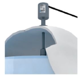
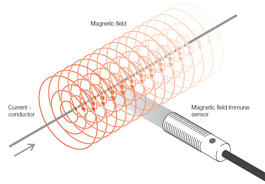
WFI sensors are typically needed at the weld gun side of the welding procedure when MIG welding is performed. This location is subject to Arc Blow that can cause a strong magnetic field at the weld wire tip location. This is the hottest location in the weld cell and typically there is an Inductive Sensor located at the end of this weld tooling.

So as you can see if a WFI sensor is not selected where there is a magnetic field present it can cause multiple cycle time problems and unnecessary downtime. For more information on WFI sensors click here.

There’s more than just one miniature sensor technology

As I discussed in my last blog post, there is a need for miniature, precision sensors. However, finding the right solution for a particular application can be a difficult process. Since every sensor technology has its own strengths and weaknesses, it is vital to have a variety of different sensor options to choose from.

The good news is that there are several different technologies to consider in the miniature, precision sensor world. Here we will briefly look at three technologies: photoelectric, capacitive, and inductive. Together these three technologies have the ability to cover a wide range of applications.

Photoelectric Sensors

MiniPhotoelectricPhotoelectric sensors use a light emitter and receiver to detect the presence or absence of an object. This type of sensor comes in different styles for flexibility in sensing. A through-beam photoelectric is ideal for long range detection and small part detection. Whereas a diffuse photoelectric is ideal for applications where space is limited or in applications where sensing is only possible from one side.

Miniature photoelectric sensors come with either the electronics fully integrated into the sensor or as a sensor with separate electronics in a remote amplifier.

Capacitive Sensors

MiniCapacitiveCapacitive sensors use the electrical property of capacitance and work by measuring changes in this electrical property as an object enters its sensing field. Capacitive sensors detect the presence or absence of virtually any object with any material, from metals to powders to liquids. It also has the ability to sense through a plastic or glass container wall to detect proper fill level of the material inside the container.

Miniature capacitive sensors come with either the electronics fully integrated into the sensor or as a sensor with separate electronics in a remote amplifier.

Inductive Sensors

MiniInductiveInductive sensors use a coil and oscillator to create a magnetic field to detect the presence or absence of any metal object. The presence of a metal object in the sensing field dampens the oscillation amplitude. This type of sensor is, of course, ideal for detecting metal objects.

Miniature inductive sensors come with the electronics fully integrated into the sensor.

One sensor technology isn’t enough since there isn’t a single technology that will work across all applications. It’s good to have options when looking for an application solution.

To learn more about these technologies, visit www.balluff.us

Liquid Level Sensing: Detect or Monitor?

Pages upon pages of information could be devoted to exploring the various products and technologies used for liquid level sensing and monitoring.  But we’re not going to do that in this article.  Instead, as a starting point, we’re going to provide a brief overview of the concepts of discrete (or point) level detection and continuous position sensing.

 Discrete (or Point) Level Detection

Example of discrete sensors used to detect tank level

In many applications, the level in a tank or vessel doesn’t need to be absolutely known.  Instead, we just need to be able to determine if the level inside the tank is here or there.  Is it nearly full, or is it nearly empty?  When it’s nearly full, STOP the pump that pumps more liquid into the tank.  When it’s nearly empty, START the pump that pumps liquid into the tank.

This is discrete, or point, level detection.  Products and technologies used for point level detection are varied and diverse, but typical technologies include, capacitive, optical, and magnetic sensors.  These sensors could live inside the tank outside the tank.  Each of these technologies has its own strengths and weaknesses, depending on the specific application requirements.  Again, that’s a topic for another day.

In practice, there may be more than just two (empty and full) detection points.  Additional point detection sensors could be used, for example, to detect ¼ full, ½ full, ¾ full, etc.  But at some point, adding more detection points stops making sense.  This is where continuous level sensing comes into play.

Continuous Level Sensing

Example of in-tank continuous level sensor

If more precise information about level in the tank is needed, sensors that provide precise, continuous feedback – from empty to full, and everywhere in between – can be used.  This is continuous level sensing.

In some cases, not only does the level need to be known continuously, but it needs to be known with extremely high precision, as is the case with many dispensing applications.  In these applications, the changing level in the tank corresponds to the amount of liquid pumped out of the tank, which needs to be precisely measured.

Again, various technologies and form factors are employed for continuous level sensing applications.  Commonly-used continuous position sensing technologies include ultrasonic, sonic, and magnetostrictive.  The correct technology is the one that satisfies the application requirements, including form factor, whether it can be inside the tank, and what level of precision is needed.

At the end of the day, every application is different, but there is most likely a sensor that’s up for the task.

Trending Now: Miniature Sensors

Celebrating the Holiday season is one of my favorite times of the year. Some of the common activities I enjoy include spending time with family and friends, eating a tremendous amount of food (and wondering afterward why I do this to myself year after year), and giving and receiving a few presents. Let’s focus on the presents aspect for a second. The bigger the present the better, right? Well, we know that’s not always the case. That smaller present could very well be the perfect gift.

minifamilyNow let’s shift gears and look at manufacturing. There is a trend in manufacturing, in general, toward miniaturization. Earlier this year I was shown a website, MICRO Manufacturing, that looks across different industries to see how the miniaturization trend is being engaged. One of the more obvious cases is in consumer electronics. It all started taking off with the desktop computer. Following the desktop computer was the laptop. And in the past few years we’ve seen the rise of smartphones and tablets. Now we’re beginning to see smart wearable devices (watches, fitness trackers, glasses, etc.). Who knows what will happen next? I bet we could take a good guess: it’ll be something even smaller.

As manufacturing continues in this direction, the demand for miniature sensors grows. However, miniature sensors aren’t just defined by their small form factor, but also by their precision. Miniature sensors are developed with a clear purpose to meet these manufacturing requirements. For more information, please click here.

And, just like that small present during the Holidays, a miniature, precision sensor could be the perfect solution.