Difficulties Faced in Externally Mounted Magnetic Transducer Applications

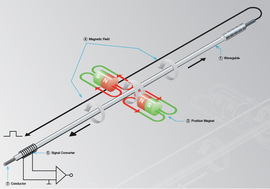
In a previous blog post, we looked at the basic operating principle of magnetostriction and how it is applied in a linear position transducer. In this post we’re going to take a more in-depth look at this popular sensing technique and the factors that can contribute to its usability in transducer applications.

magnetostricive response
Figure 1: Magnetostrictive response (λ) as the absolute value of the Magnetic Field (H) changes.

As we’ve seen, the magnetostrictive effect is produced using a permanent magnet that is fixed either around or mounted some distance away from the ferromagnetic alloy that is being used. Now, if you’re like me and you’ve spent countless nights lying awake wondering how the effect of magnetostriction in a transducer is changed by the strength of the applied magnetic field and how that pertains to the output of a magnetostrictive transducer, then there isn’t need to look much further than this blog post. The strength of the magnetic field (which is directly related to distance through an inverse cubed relationship) projected onto the ferromagnetic material plays an incredibly critical role in the effect of magnetostriction. In Figure 1 you can see a depiction of the how the magnetostrictive effect varies at differing values of magnetic field strength.

Since magnetostriction does not behave perfectly linearly, some consideration must be taken into account when choosing a magnet and mounting system for your transducer. Potential problems occur if the magnet is mounted too far away from or too close to the transducer (thus producing either too much or too little magnetic field). But before we explore why too much or too little magnetic field is a problem, let’s compare it to the most desirable magnetic conditions.

Figure 2: Standard Application in which a magnet is in a fixed position therefore, allowing no variance in the strength of the magnetic field seen by the ferromagnetic material.

Ideally, the goal is to choose a magnet and mounting distance which can produce a magnetic field that will fall within the green region from Figure 1. In this region, the magnetostrictive effect can be approximated as linear, thus being used to produce a strong and consistently predictable output response. As for what actual magnetic field strength values fall within this range, that is almost entirely dependent on the properties of the ferromagnetic alloy that you are using. In a standard application, for instance, one in which a magnet and transducer is fixed inside of a hydraulic cylinder where the magnet is mounted in a fixed position relative to the transducer rod (as shown in Figure 2.), this magnetic field value will not vary so there is no reason to worry about how the magnetostrictive response could vary. The device is designed to operate in Figure 1’s green region.

Figure 3: Externally mounted magnets that are not fixed to the transducer typically need to have stronger magnetic properties for the field to reach the device. However, if it is too strong the magnetostrictive effect can saturate and cause a loss of output.

Problems can arise when dealing with externally mounted transducers in which the user has a significant amount more freedom in the selection of magnet and its mounting design. These instances could look incredibly different depending on the application. However, Figure 3 shows how this sort of design would come into play in a “floating” magnet application. At greater distances or when using weaker, non-standard magnets, the magnetic field will fall into the first red zone on Figure 1. In this region, the magnetic strength is too weak for a signal to be processed as an output by the transducer. This is primarily caused by the effect of magnetic hysteresis which is essentially a “charge up” zone and creates an exponential relationship in this zone, rather than the desired linear relationship. On the other hand, if you attempt to use a strong, rare-earth magnet too close to the transducer, it will produce too strong of a magnetic field and move beyond the green region into the second red zone. The problem here is that the magnetostriction will saturate and can potentially cause output loss. Also, similarly to the weaker magnetic field strength, the behavior cannot be approximated using the same linear relationship that we see in the green zone of Figure 1. As with the green region of the graph, the magnetic field strength values that lie in the red zones are dependent on the properties of the material as well as the response processing electronics of the transducer.

Due to these issues, there are many things to consider if you’re using an externally mounted transducer and choosing a non-standard mounting method in your application. You need to be careful when mounting a magnet too far away or using a rare-earth magnet too close to the transducer.

For more information visit www.balluff.us.

IO-Link Sensors in Tire Manufacturing

Much has been written here on Sensortech about IO-Link, and the advantages that an IO-Link-based architecture offers. In this article, we’ll take a look at a specific application where those IO-Link advantages are clear.

Tire manufacturing machinery in general, and tire curing presses in particular, incorporate numerous sensors and indicators that contribute to machine efficiency. As an example, tire curing presses often use magnetostrictive linear position sensors for feedback and control of mold open/close. Overwhelmingly, sensors that provide an analog, 4-20 mA signal are used. But maybe there’s a better alternative to typical analog feedback.

As discussed HERE and HERE, migration away from typical analog sensor signals to network-capable IO-Link interfaces makes a great deal of sense in many areas of application.

In a tire manufacturing operation, there are typically numerous, essentially identical curing presses, lined up in a row, all doing essentially the same job. Each press uses multiple analog position sensors that need each need to be connected to the press control system. As with pretty much analog device, the use of individual shielded cables is critical. Individual shielded cables for every sensor is a costly a time-consuming proposition. An Engineering Manager at a machine builder told us recently that wiring each press requires around 300 man hours(!), a significant portion of which is spent on sensor and indicator wiring.

Which brings us to IO-Link. Replacing those analog sensors with IO-Link sensors, allows feedback signals from multiple machines to be consolidated into single cable runs, and connected to the network, be it Ethernet/IP, EtherCat, Profinet, or Profibus. The benefits of such an approach are numerous:

  • Wiring is simple and much more economical
    • Eliminates need for shielded sensor cables
  • Integrated diagnostics allow remote machine status monitoring
  • Reduces more expensive analog IO on the controller side
  • Over-the-network configuration and the ability to store those configurations reduces setup time

And, by the way, the IO-Link story doesn’t end with position sensors. The ever-growing list of IO-Link enabled sensors and indicators allows the benefits to be rolled into many areas of machine automation, such as:

  • Intelligent IO-Link power supplies with HeartBeat technology that monitor their own “health” and report it back over the network (think Predictive Maintenance)
  • Highly-configurable IO-Link stack light alternatives that can be set up to display a number of machine and process condition states
  • IO blocks, memory modules, pressure sensors, discrete (on/off) sensors of all type, and more

To learn more about IO-Link, visit Balluff.com

Stop the Scrap

steelmanufacturingIn the current era of steel production, steel manufacturers employ a continuous process during the casting phase of production. The molten steel is solidified during this process by a continuous casting machine. The processes include feeding the liquid steel through a series of rollers to cool the material and slowly form into the next shape of production (e.g. slabs, round, etc…). In this process, the rollers are positioned using hydraulic cylinders that include linear position sensors as closed loop feedback devices. The outputs of these sensors are closely monitored and are critical to the steel quality. Because of the harsh environment of the continuous casting process, the life span of these sensors can be cut short. If the sensor’s output becomes unstable and begins to fail, the continuous casting process cannot simply stop quickly. The steel quality during this sensor failure mode will most likely become scrap, costing the steel mill tens of thousands of dollars.

btl7-t-redundant-seriesFor maximum reliability, a linear position sensor with 2 or 3 times redundancy can be utilized to provide position feedback of hydraulic systems. Such sensors employ 2 or 3 independently-operating sensing elements and processing circuitry . The extra feedback signals can be monitored through an automation system. When the outputs are compared, a failure could be identified early and the automation system could switch over to the reliable output maintaining the quality of steel. No scrap! During the next possible scheduled stoppage in the manufacturing process, the sensor could be replaced.

For more information on Balluff solutions for the metallurgy industry, start here.

For more information, visit www.balluff.com.

Harsh Industrial Environments Challenge Plant Operators

Most industrial processes do not take place in a climate-controlled laboratory or clean room environment. Real-world industrial activity generates or takes place under harsh conditions that can damage or shorten the life expectancy of equipment, especially electronic sensors.

A cross-section of industrial users was surveyed about operating conditions in their facilities. The responses revealed that plant operators are challenged by a variety of difficult environmental factors, the biggest being heat, dust/dirt/water contamination, vibration, and extreme temperature swings.

linearpositionsensorinfographic

Over one-third of the industrial users surveyed reported that premature sensor failure is a problem in their operations. That is a surprisingly high percentage and something that needs to be addressed to restore lost productivity and maintain long-term competitiveness.

Many heavy industries are dependent on automated hydraulic cylinders to move and control large loads precisely. The cylinder position sensors are often subjected to damaging environmental conditions that shorten their life expectancy, leading to premature failure.

Fortunately, there are measures that can be taken to reduce or eliminate the occurrence of sensor-related downtime. Help is available in the form of a free white paper from Balluff called “Improving the Reliability of Hydraulic Cylinder Position Sensors”.

To learn more about this topic you can also visit www.balluff.us.

External Linear Position Sensors: Floating or Captive Magnet?

External Linear Position Sensors:  Floating or Captive Magnet? 
PFMagnetsLinear position sensors that are designed to be mounted externally on a machine (as opposed to those designed to be installed into a hydraulic or pneumatic cylinder) are available in a variety of form factors that suit a variety of different applications and application requirements.  One of the most common form factors, particularly for magnetostrictive linear position sensors, is a rectilinear aluminum extrusion that houses the sensing element, or waveguide, and the processing electronics.  Commonly, you’ll hear these referred to as profile-style linear position sensors.

CaptiveVSFloating
Captive magnet (left) and floating magnet (right)

With these types of sensors, the moving part of the machine to be measured or monitored is attached to a position magnet.  The position magnet can be either captive or floating (see image to the right).  Each of these magnet configurations offer some inherent advantages.  We’re going to take a closer look at each.

Captive Magnet

A captive magnet glides along in a track that is an integral part of the extruded aluminum sensor housing.  The magnet is attached to the moving part of the machine via a mechanical linkage.  Advantages of a captive magnet arrangement include:

  • Mechanical flexibility: The magnet usually incorporates an articulating swivel or ball joint that is attached via a linking rod to the moving machine part.  That means the sensor doesn’t need to be perfectly in line with the axis of movement.
  • Protection from damage – In some cases, it is necessary to move the sensor out of harm’s way (e.g., extreme heat, caustic chemicals, strong electromagnetic fields, etc.). The linkage can be as long as necessary in order to connect to the sensor, which will be located in a more hospitable environment.

Some things to consider when choosing to use a captive magnet configuration:

  • Binding of the magnet: A high-quality magnetostrictive sensor is going have a near-zero drag coefficient between magnet and extrusion.  The magnet should not bind or drag.  But in some applications, dirt, grease and particulates can accumulate and cause issues.  For these applications, a floating magnet may be a better choice.
  • Mechanical overtravel:  In a captive magnet arrangement, if the machine travel exceeds the physical length of the sensor, the magnet will (of course) fall off the track.  If this is a concern, consider a floating magnet instead.

Floating Magnet

In a floating magnet arrangement, the sensor is located adjacent to the moving machine part.  The magnet is attached to that machine part, usually on a rigid arm or bracket.  Advantages of a floating magnet include:

  • No mechanical contact: The magnet never makes contact with the housing.  This could be important in applications where dirt, grease or particulates tend to collect on the sensor (see photo below)
    harshenvironment
  • Machine overtravel: Since the magnet is completely uncoupled from the sensor, machine overtravel isn’t a problem.  Obviously, if the magnet leaves the sensor, position feedback is lost, but the sensor will resume normal operation once the magnet re-enters the sensor’s range.

Some things to consider when choosing a floating magnet configuration:

Magnet-to-sensor gap:  In some cases the movement of the machine does not allow a consistent magnet-to-sensor gap to be maintained.  In some sensors, this can lead to inconsistent or erratic sensor operation.  Fortunately, there are sensors available with innovative technology that automatically compensates for such gap fluctuations and maintain full performance and specifications even as the gap varies.  Click below to see such technology in action.

Ultimately, the choice between a floating magnet and a captive magnet arrangement is going to be driven by the requirements of your particular application.

Click the link for more information on external-mount linear position sensors.

Quick field replacement for linear sensor electronics

Micropulse Transducers BTL 7 Rod-style with Rapid Replacement Module
Micropulse Transducers BTL 7
Rod-style with Rapid Replacement Module

When maintenance technicians replace linear position sensors (also known as probes or wands) from hydraulic cylinders, it can leave a terrible mess, waste hydraulic oils, and expose the individual to harmful hot fluids.  Also, the change out process can expose the hydraulic system to unwanted contaminants. After the sensor replacement has been completed, there can also be more work yet to do during the outage such as replacing fluids and air-bleeding cylinders.

Hydraulic linear position sensors with field-replaceable electronics/sensing elements eliminate these concerns.  Such sensors, so-called Rapid Replacement Module (RRM) sensors, allow the “guts” of the sensor to be replaced, while the stainless steel pressure tube remains in the cylinder.  The hydraulic seal is never compromised.  That means that during the replacement process there is no danger of oil spillage and no need for environmental containment procedures. There is also no need to bleed air from the hydraulic system and no danger of dirt or wood debris entering the open hydraulic port. Finally, there is no danger of repair personnel getting burned by hot oil.

The RRM is an option for Balluff’s BTL7 Z/B Rod Series used in applications for the lumber industry, plastic injection and blow molding, tire and rubber manufacturing, stamping presses, die casting, and all types of automated machinery where a continuous, absolute position signal is required.  Applications in industries such as Oil & Gas and Process Control are especially critical when it comes to downtime.  For these applications, this Rapid Replacement Module capability is especially advantageous.

You can learn more about linear position sensors with hazardous area approvals, by visting http://www.balluff.com/local/us/products/sensors/magnetostrictive-linear-position-sensors/

The video below shows a demonstration of the Rapid Replacement Module in action.


A superior non-contact sensing principle

MagnetostrictionImageMagnetostriction is a property of ferromagnetic (iron-based, magnetizeable) materials that causes them to change their shape or dimensions in the presence of a magnetic field. In addition to numerous other practical uses, this magnetostrictive effect is ideally suited for use in industrial linear position measurement sensors. Magnetostrictive linear position sensors use an iron-alloy sensing element, typically called a waveguide. Referring to the diagram at right, the waveguide (1) is housed inside a pressure-rated stainless steel tube or in an aluminum extrusion. The position magnet (2) is attached to the moving part of the machine, or the piston of a hydraulic or pneumatic cylinder. Measurements are initiated by applying a short-duration electrical pulse to a conductor (3) attached to the waveguide. The current creates a magnetic field (4) along the waveguide.

The magnetic field from the position magnet interacts with the generated magnetic field, inducing a torsional mechanical strain on the waveguide. When the current pulse stops, the strain is released, causing a mechanical pulse to propagate along the waveguide. This mechanical pulse travels at a constant speed, and is detected at the signal converter (5).

The time between the initial electrical pulse and the received mechanical pulse accurately represents the absolute position of the position magnet and, ultimately position of the machine or hydraulic cylinder. The position of the magnet along the waveguide is calculated by very accurately timing the interval between the initial current pulse, also known as the Interrogation Pulse, and the detection of the mechanical return pulse.

Blaise Pascal – The Ultimate Powerlifter

Our modern technological society owes a lot to the scientific work and inspiration of a 17th-century French mathematician and physicist, Blaise Pascal. Pascal was a pioneer in the fields of hydrostatics and hydrodynamics, which deal with the subject of fluid mechanics under pressure.

One of the most important physical principles he defined is known today as Pascal’s Law:

“Blaise Pascal Versailles” by unknown1

“A change in pressure at any point in an enclosed fluid at rest is transmitted undiminished to all points in the fluid.”

It is this characteristic of fluids held in containment that allows force applied to a fluid in one location to be delivered to another remote location. A well-known example would be the hydraulic brake system in a car. Mechanical pressure from the driver’s foot is transferred to the brake fluid through a master cylinder. This pressure is then instantly communicated to braking cylinders located at each wheel, causing them to apply mechanical force to press friction pads against a brake drum or rotor, thus slowing or stopping the vehicle.

In the industrial world, the compact yet incredible power of hydraulic cylinders is a constant source of awe and amazement. Through the magic of fluid power leverage via Pascal’s Law, hydraulic cylinders are capable of generating tremendous lifting forces to move massively heavy structures.

In order for such great force to be harnessed to do useful work, it must be kept fully under control. Force that is out of control is either useless or destructive. When it comes to controlling the movement of a powerful hydraulic cylinder, the piston/ram position must be continually monitored in near-real-time.

The most popular device for measuring cylinder position is called a Magnetostrictive Linear Position Sensor. Sometimes these position sensors are called LDTs (Linear Displacement Transducer) or MDTs (Magnetostrictive Displacement Transducer). All of these terms refer to the same type of devices.

BTL7

To get an idea of the power and control that is feasible with modern hydraulic cylinders and integrated cylinder position sensors, have a look at this amazing video from ALE Heavylift. The topside of a giant offshore oil platform was jacked up 131 ft (40 m) and then skidded horizontally a distance of 295 ft (90 m) to place it on top of its supports. Imagine the incredible synchronization of speed, position, and operational sequencing needed to safely lift and place such a massive structure.

For more information about magnetostrictive linear position sensors for hydraulic cylinders, visit the Balluff website at www.balluff.us.

1. “Blaise Pascal Versailles” by unknown; a copy of the painture of François II Quesnel, which was made for Gérard Edelinck en 1691. – Own work. Licensed under CC BY 3.0 via Commons – https://commons.wikimedia.org/wiki/File:Blaise_Pascal_Versailles.JPG#/media/File:Blaise_Pascal_Versailles.JPG

Back to the Basics: How Do I Wire a DC 2-wire Sensor?

In one of my previous post we covered “How do I wire my 3-wire sensors“. This topic has had a lot of interest so I thought to myself, this would be a great opportunity to add to that subject and talk about DC 2-wire sensors. Typically in factory automation applications 2 or 3 wire sensors are implemented within the process, and as you know from my prior post a 3 wire sensor has the following 3 wires; a power wire, a ground wire and a switch wire.

A 2-wire sensor of course only has 2 wires including a power wire and ground wire with connection options of Polarized and Non-Polarized. A Polarized option requires the power wire to be connected to the positive (+) side and the ground wire to be connected to the negative side (-) of the power supply. The Non-Polarized versions can be wired just as a Polarized sensor however they also have the ability to be wired with the ground wire (-) to the positive side and the power wire (+) to the negative side of the power supply making this a more versatile option as the sensor can be wired with the wires in a non – specific location within the power supply and controls.

In the wiring diagrams below you will notice the different call outs for the Polarized vs. Non-Polarized offerings.

PolarizedDiagramsnon-polarized diagramsNote: (-) Indication of Non-Polarized wiring.

While 3-wire sensors are a more common option as they offer very low leakage current, 2 wire offerings do have their advantages per application. They can be wired in a sinking (NPN) or sourcing (PNP) configuration depending on the selected load location. Also keep in mind they only have 2 wires simplifying connection processes.

For more information on DC 2- Wire sensors click here.

Linear Position Sensors for Valve Actuators

Illustration of Magnetostrictive Linear Displacement Transducer (MLDT) inserted into a gun-drilled cylinder.Today’s petrochemical and process industries, like most industries, are striving to increase their capabilities of automation & control, coupled with condition monitoring, across their entire operation.  Demands for uptime are increasing and the focus on reliability through redundancy and prediction of pending maintenance requires new control and monitoring strategies.  This is nowhere more true than in the case of the sophisticated valves that form the most critical elements of the operation or process.  Operational readiness and confirmation of operation for these valves are indispensable to assure smoother and uninterrupted production…and safety.

Christian Dow has written an interesting article in Valve Magazine that highlights the benefits of linear position sensors when installed in the hydraulic actuators of these valves.  The benefits mentioned in the article don’t apply just for valves, though.  Many of the advantages can be obtained for almost any application where a hydraulic cylinder is the prime mover.