Distance Measurement with Inductive Sensors

When we think about inductive sensors we automatically refer to discrete output offerings that detect the presence of ferrous materials. This can be a production part or an integrated part of the machine to simply determine position. Inductive sensors have been around for a long time, and there will always be a need for them in automated assembly lines, weld cells and stamping presses.

We often come across applications where we need an analog output at short range that needs to detect ferrous materials. This is an ideal application for an analog inductive proximity sensor that can offer an analog voltage or analog current output. This can reliably measure or error proof different product features such as varying shapes and sizes. Analog inductive sensors are pure analog devices that maintain a very good resolution with a high repeat accuracy. Similar to standard inductive sensors, they deal very well with vibration, commonly found in robust applications. Analog inductive proximity sensors are also offered in many form factors from M12-M30 tubular housings, rectangular block style and flat housings. They can also be selected to have flush or non-flush mounting features to accommodate specific operating distances needed in various applications.

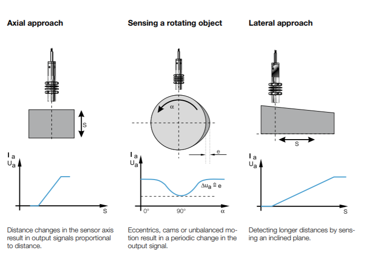
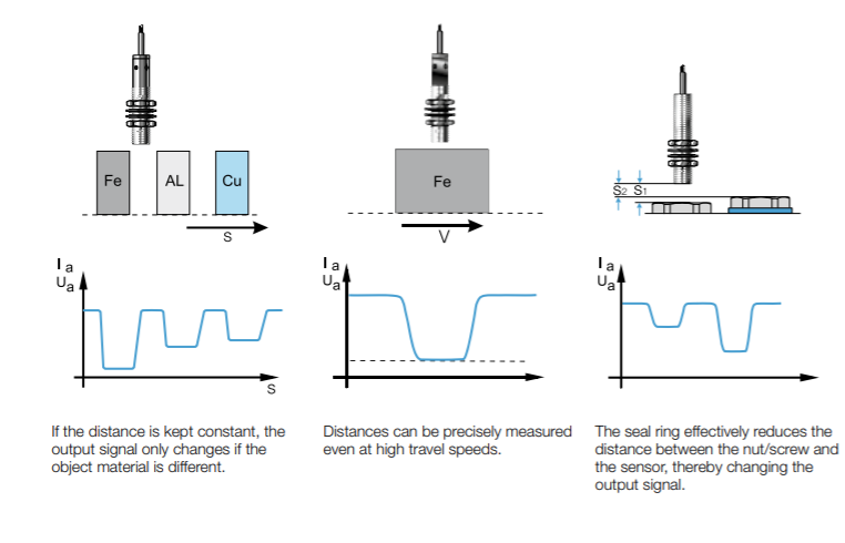
Application Examples:

Shawn_1.png

Shawn_2

For more specific information on analog inductive sensors visit www.balluff.com.

Reliable Part Exit/Part-Out Detection

Walk into any die shop in the US and nine out of ten times, we discover diffuse reflective sensors being used to detect a large part or a small part exiting a die. Many people have success using this methodology, but lubrication-covered tumbling parts can create challenges for diffuse-reflective photoelectric sensing devices for many reasons:

  1. Tumbling parts with many “openings” on the part itself can cause a miss-detected component.
  2. Overly-reflective parts can false triggering of the output.
  3. Dark segments of the exiting part can cause light absorption. Remember, a diffuse sensors sensing distance is based on reflectivity. Black or dark targets tend to absorb light and not reflect light back to the receiver.
  4. Die lube/misting can often fog over a photoelectric lens requiring maintenance or machine down time.

The solution: Super Long Range Inductive Sensors placed under chutes

Most metal forming personnel are very familiar with smaller versions of inductive proximity sensors in tubular sizes ranging from 3mm through 30mm in diameter and with square or “block style” inductive types (flat packs, “pancake types”, etc.) but it is surprising how many people are just now discovering “Super Long Range Inductive Proximity” types. Super Long Range Inductive Proximity Sensors have been used in metal detection applications for many years including Body-In-White Automotive applications, various segments of steel processing and manufacturing, the canning industry, and conveyance.

Benefits of Using A UHMW Chute + Super Long Range Inductive Proximity Sensor in Part Exit/Part-Out Applications:

  1. It is stronger and quieter than parts flowing over a metal chute, readily available in standard and custom widths, lengths and thicknesses to fit the needs of large and small part stampers everywhere.
  2. UHMW is reported to be 3X stronger than carbon steel.
  3. UHMW is resistant to die lubes.
  4. UHMW allows Super Long Range Inductive Proximity Sensors to be placed underneath and to be “tuned” to fit the exact zone dimension required to detect any part exiting the die (fixed ranges and tunable with a potentiometer). The sensing device is also always out of harm’s way.
  5. Provides an option for part detection in exiting applications that eliminates potential problems experienced in certain metal forming applications where photoelectric sensing solutions aren’t performing optimally.
A Two-Out Die with Metallic Chute

Not every Part Exit/Part-Out application is the same and not every die, stamping application, vintage of equipment, budget for sensing programs are the same. But it’s important to remember in the world of stamping, to try as consistently as possible to think application specificity when using sensors.  That is, putting the right sensing system in the right place to get the job done and to have as many technical options available as possible to solve application needs in your own “real world” metal forming operation.  We believe the UHMW + Super Long Range Inductive System is such an option.

You can learn more in the video below or by visiting www.balluff.us.

Reed Switches vs. Magnetoresistive Sensors (GMR)

In a previous post we took a look at magnetic field sensors vs inductive proximity sensors for robot grippers. In this post I am going to dive a little deeper into magnetic field sensors and compare two technologies: reed switches, and magnetoresistive sensors (GMR).

Reed Switches

PrintThe simplest magnetic field sensor is the reed switch. This device consists of two flattened ferromagnetic nickel and iron reed elements, enclosed in a hermetically sealed glass tube. As an axially aligned magnet approaches, the reed elements attract the magnetic flux lines and draw together by magnetic force, thus completing an electrical circuit.

While there are a few advantages of this technology like low cost and high noise immunity, those can be outweighed by the numerous disadvantages. These switches can be slow, are prone to failure, and are sensitive to vibration. Additionally, they react only to axially magnetized magnets and require high magnet strength.

Magnetoresistive Sensors (GMR)

PrintThe latest magnetic field sensing technology is called giant magnetoresistive (GMR). Compared to Reed Switches GMR sensors have a more robust reaction to the presence of a magnetic field due to their high sensitivity, less physical chip material is required to construct a practical GMR magnetic field sensor, so GMR sensors can be packaged in much smaller housings for applications such as short stroke cylinders.

GMR sensors have quite a few advantages over reed switches. GMR sensors react to both axially and radially magnetized magnets and also require low magnetic strength. Along with their smaller physical size, these sensors also have superior noise immunity, are vibration resistant. GMR sensors also offer protection against overload, reverse polarity, and short circuiting.

Basic Sensors for Robot Grippers

Robot gripper with inductive proximity sensors mounted

Typically when we talk about end-of-arm tooling we are discussing how to make robot grippers smarter and more efficient. We addressed this topic in a previous blog post, 5 Tips on Making End-of-Arm Tooling Smarter. In this post, though, we are going to get back to the basics and talk about two options for robot grippers: magnetic field sensors, and inductive proximity sensors.

One of the basic differences is that detection method that each solution utilizes. Magnetic field sensors use an indirect method by monitoring the mechanism that moves the jaws, not the jaws themselves. Magnetic field sensors sense magnets internally mounted on the gripper mechanism to indicate the open or closed position. On the other hand, inductive proximity sensors use a direct method that monitors the jaws by detecting targets placed directly in the jaws. Proximity sensors sense tabs on moving the gripper jaw mechanism to indicate a fully open or closed position.

BMF_Grippers
Robot gripper with magnetic field sensors mounted

Additionally, each solution offers its own advantages and disadvantages. Magnetic field sensors, for example, install directly into extruded slots on the outside of the cylinder, can detect an extremely short piston stroke, and offer wear-free position detection. On the other side of the coin, the disadvantages of magnetic field sensors for this application are the necessity of a magnet to be installed in the piston which also requires that the cylinder walls not be magnetic. Inductive proximity sensors allow the cylinder to be made of any material and do not require magnets to be installed. However, proximity sensors do require more installation space, longer setup time, and have other variables to consider.

The Latest Trend in the Stamping and Die Industry

compact-sensor-blogOne trend we see today in many applications is the need for smaller low profile proximity sensors. Machines are getting much smaller and the need for error proofing has ultimately become a must for such applications in the Stamping and Die industry. Stamping Die processes can be a very harsh environment with excessive change overs to high speed part feed outs when running production. In many cases these applications need a sensor that can provide 5mm of sensing range however they simply do not have the room for an M18 sensor that is 45 to 50mm long. This is where the “FlatPack” low profile sensor can be a great choice due to their low profile dimensions.

Proximity sensors have proven time and time again to reduce machine crashes, part accuracy and proper part location. Sensors can be placed in multiple locations within the application to properly error proof “In Order Parts” (IO) for example detecting whether a punched hole is present or not present to ensure a production part is good. All of this adds up to reduced machine downtime and lower scrap rates that simply help a plant run more efficiently.

So when selecting proximity sensors and mating cables it is very important to select a sensor that A) mechanically fits the application and B) offers enough sensing range detection to reliably see the target without physical damage to the sensor. Remember, these sensors are proximity sensors not positive machine stops. Cables are also key to applications, it is important to pick a the proper cable needed for example an abrasion resistant cable may be needed due to excessive metal debris or a TPE cable for high flex areas.

Below both sensors have 5mm of sensing range:

M18vsFlatpack

Below both sensors have 2mm of sensing range:

M8vsFlatpack

You can see that in certain process areas “FlatPack” low profile sensors can provide benefits for applications that have space constraints.

For more information on proximity sensors click here.

Inductive Sensors for Washdown Conditions

WashdownSensorsWhen selecting the proper Inductive sensor it is very important to understand the type of application environment the sensor will be installed in. In previous posts, I have blogged about various types of sensors and how they fit into the application mix. For example, a welding application will need specific sensor features that will help combat the normal hostilities that are common to heat, weld spatter and impact due to tight tolerances within the fixture areas.

Inductive sensors are also used more and more in aggressive environments including machine tools, stamp and die, and food and beverage applications. Many times within these types of applications there are aggressive chemicals and cleaners that are part of the application process or simply part of the cleanup procedure that also
mandates high pressure wash down procedures.

So, when we have a stamping or food and beverage application that uses special oils or coolants we know a standard sensor is on borrowed time. This is where harsh environment sensors come in as they offer higher IP ratings with no LED function indicators that seals the sensor to withstand the harshest processes. They also will have high grade stainless steel housings special plated electronics along with additional O-rings making them ideal for the most hostile environment.

InductiveWashdownFeatures:

  • High grade stainless steel housing
  • No LED indicator
  • Gold plated internal contacts
  • Additional sealing O-rings
  • Increased IP ratings
  • Higher temperature ratings

For more information on inductive sensors for harsh environments you can visit the Balluff website at www.balluff.us.

High Pressure Inductive Sensors with Analog Feedback

In my previous blog post we covered the Anatomy of a High Pressure Proximity Sensor. That post covered the different mechanical housing designs and special properties that go into high pressure sensor products with discrete outputs. That is great information to know when specifying the correct sensor for a particular application. In today’s competitive market and constant goals to improve processes, sensor’s that offer continuous feedback are required.

Hydraulic systems regulate speed of an actuator by regulating flow rate. The flow rate determines the speed of the cylinder spud that actuates inside the system. For example, an analog sensor can provide measurement to the controls with indication of slowing down or speeding up the actuator based on the analog feedback from the sensor in regard to position of the tapered section of the actuator. So, if the internal target gets larger with more position movement (stroke) the distant measurement changes and indicates that the end of stroke is near causing the controller to initiate a soft stop. This provides better control of the system offering a more efficient reliable process.

500barAnalog Inductive sensors provide an absolute voltage or current signal change proportional to the distance of a ferrous target. In high pressure applications that require more position feedback, an analog distance sensor can offer a solution as they also offer high – strength stainless steel housings with special sealing designs that allow pressure up to 500 bar and 85°C temperature ratings making them an ideal solution for valve speed control and soft starts with a non – contact design.

More information on high pressure analog inductive sensors is available on the Balluff website at www.balluff.us.

Let’s Get Small: The Drive Toward Miniaturization

minisensorGoing about our hectic daily lives, we tend to just take the modern cycle of innovation for granted. But when we stop to think about it, the changes we have seen in the products we buy are astonishing. This is especially true with regard to electronics. Not only are today’s products more feature-laden, more reliable, and more functional…they are also unbelievably small.

I remember our family’s first “cell phone” back in the ’90s. It was bolted to the floor of the car, required a rooftop antenna, and was connected to the car’s electrical system for power. All it did was place and receive phone calls. Today we are all carrying around miniature pocket computers we call “smartphones,” where the telephone functionality is – in reality – just another “app”.

Again going back two decades, we had a 32″ CRT analog television that displayed standard definition and weighed over 200 pounds; it took two strong people to move it around the house. Today it’s common to find 55″ LCD high-definition digital televisions that weigh only 50 pounds and can be moved around by one person with relative ease.

LabPhotoThese are just a couple of examples from the consumer world. Similar changes are taking place in the industrial and commercial world. Motors, controllers, actuators, and drives are shrinking. Today’s industrial actuators and motion systems offer either the same speed and power with less size and weight, or are simply more compact and efficient than ever before possible.

The advent of all this product miniaturization is driving a need for equally miniaturized manufacturing and assembly processes. And that means rising demand for miniaturized industrial sensors such as inductive proximity sensors, photoelectric presence sensors, and capacitive proximity sensors.

Another thing about assembling small things: the manufacturing tolerances also get small. The demand for sensor precision increases in direct proportion to manufacturing size reduction. Fortunately, miniature sensors are also inherently precision sensors. As sensors shrink in size, their sensing behavior typically becomes more precise. In absolute terms, things like repeatability, temperature drift, and hysteresis all improve markedly as sensor size diminishes. Miniature sensors can deliver the precise, repeatable, and consistent sensing performance demanded by the field of micro-manufacturing.

For your next compact assembly project, be sure to think about the challenges of your precision sensing applications, and how you plan to deploy miniature sensors to achieve consistent and reliable operation from your process.

For more information on precision sensing visit balluff.us/minis.

Back to the Basics: How Do I Wire a DC 2-wire Sensor?

In one of my previous post we covered “How do I wire my 3-wire sensors“. This topic has had a lot of interest so I thought to myself, this would be a great opportunity to add to that subject and talk about DC 2-wire sensors. Typically in factory automation applications 2 or 3 wire sensors are implemented within the process, and as you know from my prior post a 3 wire sensor has the following 3 wires; a power wire, a ground wire and a switch wire.

A 2-wire sensor of course only has 2 wires including a power wire and ground wire with connection options of Polarized and Non-Polarized. A Polarized option requires the power wire to be connected to the positive (+) side and the ground wire to be connected to the negative side (-) of the power supply. The Non-Polarized versions can be wired just as a Polarized sensor however they also have the ability to be wired with the ground wire (-) to the positive side and the power wire (+) to the negative side of the power supply making this a more versatile option as the sensor can be wired with the wires in a non – specific location within the power supply and controls.

In the wiring diagrams below you will notice the different call outs for the Polarized vs. Non-Polarized offerings.

PolarizedDiagramsnon-polarized diagramsNote: (-) Indication of Non-Polarized wiring.

While 3-wire sensors are a more common option as they offer very low leakage current, 2 wire offerings do have their advantages per application. They can be wired in a sinking (NPN) or sourcing (PNP) configuration depending on the selected load location. Also keep in mind they only have 2 wires simplifying connection processes.

For more information on DC 2- Wire sensors click here.

There’s more than just one miniature sensor technology

As I discussed in my last blog post, there is a need for miniature, precision sensors. However, finding the right solution for a particular application can be a difficult process. Since every sensor technology has its own strengths and weaknesses, it is vital to have a variety of different sensor options to choose from.

The good news is that there are several different technologies to consider in the miniature, precision sensor world. Here we will briefly look at three technologies: photoelectric, capacitive, and inductive. Together these three technologies have the ability to cover a wide range of applications.

Photoelectric Sensors

MiniPhotoelectricPhotoelectric sensors use a light emitter and receiver to detect the presence or absence of an object. This type of sensor comes in different styles for flexibility in sensing. A through-beam photoelectric is ideal for long range detection and small part detection. Whereas a diffuse photoelectric is ideal for applications where space is limited or in applications where sensing is only possible from one side.

Miniature photoelectric sensors come with either the electronics fully integrated into the sensor or as a sensor with separate electronics in a remote amplifier.

Capacitive Sensors

MiniCapacitiveCapacitive sensors use the electrical property of capacitance and work by measuring changes in this electrical property as an object enters its sensing field. Capacitive sensors detect the presence or absence of virtually any object with any material, from metals to powders to liquids. It also has the ability to sense through a plastic or glass container wall to detect proper fill level of the material inside the container.

Miniature capacitive sensors come with either the electronics fully integrated into the sensor or as a sensor with separate electronics in a remote amplifier.

Inductive Sensors

MiniInductiveInductive sensors use a coil and oscillator to create a magnetic field to detect the presence or absence of any metal object. The presence of a metal object in the sensing field dampens the oscillation amplitude. This type of sensor is, of course, ideal for detecting metal objects.

Miniature inductive sensors come with the electronics fully integrated into the sensor.

One sensor technology isn’t enough since there isn’t a single technology that will work across all applications. It’s good to have options when looking for an application solution.

To learn more about these technologies, visit www.balluff.us