Remote Power Through Inductive Coupling

Inductive couplers are reshaping industrial connectivity by enabling wireless power and data transmission across air gaps. In this blog, I explore the mechanics behind inductive couplers, from magnetic fields facilitating power transfer to bidirectional data communication. I’ll look at applications like end-of-arm tooling, rotary indexing tables, and rapid die change systems to discover how inductive couplers enhance flexibility, durability, and reliability in manufacturing. Additionally, I’ll review the benefits of this technology, poised to revolutionize wireless connectivity in industrial settings.

Inductive couplers: what they are and how they work

Inductive couplers transmit power and data wirelessly without physical connection over an air gap. They are used in various industrial applications such as end-of-arm tooling, rotary indexing tables as well and rapid die change.

Inductive couplers consist of two components: a base (transmitter) and a remote (receiver). The base is connected to a power source and a controller. The remote is attached to a load, such as a hub powering sensors or actuators. Power and data are transferred when the base and remote are in range and aligned on a common axis.

The base generates a magnetic field by passing a current through a coil. The magnetic field induces a voltage in the coil of the remote, which powers the load. The power transfer is based on the principle of electromagnetic induction, which states that a changing magnetic field creates an electric potential difference across a conductor.

The data transfer is also based on electromagnetic induction but with a different frequency and modulation scheme. The base and the remote can communicate bidirectionally by modulating the amplitude, frequency, or phase of their currents. The data signals are superimposed on the power signals and can be decoded by the controller.

Applications that can benefit from inductive coupling

Inductive coupling finds valuable applications in various scenarios, such as:

End-of-arm tooling: Inductive couplers can power and control robotic arms, grippers, or tools, without limiting their mobility or functionality. They can also enable wireless charging of autonomous robots or drones. This technology’s contribution also extends to:

    • Increased flexibility in robot movements. Since there are no physical connections, the robot can move freely without worrying about cable management or connector wear.
    • Improved durability in harsh industrial environments, as inductive couplers are typically sealed and resistant to dust, dirt, and moisture.
    • Fast tool change on robots. Since there’s no need to manually disconnect and reconnect cables, tool changes can be done quickly and efficiently.
    • More reliability than pin-based connector systems, especially for low power sensors. They can create a more stable connection, reducing the risk of signal loss or interruption.

Rotary indexing tables: Machine tool positioning devices used to move parts in programmed, increments so they can be machined or assembled. During operation, the table rotates around a central axis, stops at a predetermined location, remains in that position while an operation is performed, and then rotates to the next position. Powering sensors on a rotary indexing table can be achieved through various methods, but the most efficient way is using inductive coupling which allows for the transfer of power and data without physical contact. it is particularly useful in applications where the rotary indexing table must be able to move in complex ways.

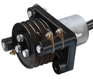
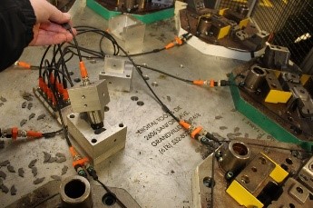
Rapid die change: The quick die change system includes a combination of a die transfer arm, die clamp, die lifter, operation box, and power pump. Through the combination of automated equipment, the product changeover time, production start-up time, or adjustment time of the mold can be minimized. Users can quickly change the mold and clamp the mold, reduce mold change time, produce a variety of small quantities, and reduce inventory and output.

Inductive coupling can be advantageous for die change in industrial automation. Stampers can integrate inductively coupled connector systems to enable rapid die change. This technology can be used for joining die segments, easing the changeout of transfer arms, and communication during transfer functions.

Disadvantages of pin style connectors. Soldered connections can be sensitive to both corrosion and vibration. The filler metal used for the soldering connection will degrade over time and can cause connection failures.

Slip rings are often used in automated assembly lines and packaging machinery, where continuous rotation is required for the system to efficiently operate. They are also used in the food and beverage industry, wind turbines, factory automation, robotics, radars, medical imaging equipment, monitoring equipment, and many others.

Despite their versatility, slip rings come with a complex construction, which includes components such as rings and brushes. These components require regular inspection, cleaning, and maintenance to ensure optimal performance. Failure to maintain slip rings and brushes properly can result in poor electrical contact, increased resistance, and reduced motor efficiency.

The presence of slip rings and brushes introduces additional points of potential wear and tear, requiring inspection, cleaning, and replacement when necessary. This increased maintenance requirement can result in higher downtime and maintenance costs compared to other motor types.

What are the benefits of using inductive couplers?

Inductive couplers offer several advantages that make them a preferred choice in various applications. One key benefit is their flexibility, as they can be easily installed and reconfigured without the need for complex wiring or connectors. Unlike traditional methods, inductive couplers allow for misalignment of up to 15-20 degrees of angular offset or 2-4mm of axial offset while still maintaining functionality.

Another notable advantage is their reliability, as they are immune to wear and tear, corrosion, vibration, or dirt that may affect the performance of standard mechanical contacts. With both the base and remote components fully encapsulated, typically featuring an IP67 protection class, environmental concerns are effectively mitigated.

Additionally, inductive couplers enhance safety by eliminating the risk of electric shocks, sparks, or short circuits commonly associated with exposed conductors or contacts. They also reduce the electromagnetic interference that can affect signal quality or damage electrical components.

Overall, the use of inductive couplers brings about a combination of flexibility, reliability, and safety, making them a valuable choice in various industrial and technological settings.

Non-Contact Inductive Couplers Provide Wiring Advantages, Added Flexibility and Cost Savings Over Industrial Multi-Pin Connectors

Today, engineers are adding more and more sensors to in-die sensing packages in stamping applications. They do so to gain more information and diagnostics from their dies as well as reduce downtime. However, the increased number of sensors also increases the number of electric connections required in the automation system. Previously, the most common technique to accommodate large numbers of sensor in these stamping applications was with large, multi-pin connectors. (Figure 1)

Figure 1
Figure 1: A large multi-pin connector has been traditionally used in the past to add more electronics to a die.

The multi-pin connector approach works in these applications but can create issues, causing unplanned downtime. These problems include:

    1. Increased cost to the system, not only in the hardware itself, but in the wiring labor. Each pin of the connector must be individually wired based on the sensor configuration of each particular die. Depending on the sensor layout of the die, potentially each connector could need to be wired differently internally.
    2. A shorter life span for the multi-pin connector due to the tough stamping environment. The oil and lubrication fluids constantly spraying on the die can deteriorate the connectors plastic housings. Figure 1 shows the housing starting to come apart. When the connector is unplugged, these devices are not rated for IP67 and dirt, oil, and/or other debris can build up inside the connector.
    3. Cable damage during typical die change out. Occasionally, users forget to unplug the connectors before pulling the die out and they tear apart the device. If the connector is unplugged and left hanging off the die, it can be run over by a fork truck. Either way, new connectors are required to replace the damaged ones.
    4. Bent or damaged pins. Being mechanical in nature, the pin and contact points will wear out over time by regular plugging and unplugging of these devices.
    5. A lack of flexibility. If an additional sensor for the die is required, additional wiring is needed. The new sensor input needs to be wired to a free pin in the connector and a spare pin may not be available.
Figure 2
Figure 2: Above is a typical set up using these multi-pin connectors hard-wired to junction boxes.

Inductive couplers (non-contact) are another solution for in-die sensors connecting to an automation system. With inductive couplers, power and data are transferred across an air gap contact free. The system is made up of a base (transmitter) and remote (receiver) units. The base unit is typically mounted to the press itself and the remote unit to the die. As the die is set in place, the remote receives power from the base when aligned and exchanges data over a small air gap.

The remote and base units of an inductive coupler pair are fully encapsulated and typically rated IP67 (use like rated cabling). Because of this high ingress protection rating, the couplers are not affected by coolant, die lubricants, and/or debris in a typical stamping application. Being inherently non-contact, there is no mechanical wear and less unplanned downtime.

When selecting an inductive coupler, there are many considerations, including physical form factors (barrel or block styles) and functionality types (power only, input only, analog, configurable I/O, IO-Link, etc…). IO-Link inductive couplers offer the most flexibility as they allow 32 bytes of bi-direction data and power. With the large data size, there is a lot of room for future expansion of additional sensors.

Adding inductive couplers can be an easy way to save on unexpected downtime due to a bad connector.

fig 3
Figure 3: A typical layout of an IO-Link system using inductive couplers in a stamping application.

Inductive Coupling: A Simple Solution for Replacing Slip Rings

1
Figure 1: Inductive coupling for power and data exchange

In the industrial automation space, inductive sensors have grown very popular , most commonly used for detecting the proximity of metal objects such as food cans, or machine parts. Inductive coupling, also known as non-contact connectors, uses magnetic induction to transfer power and data over an air gap.

2.png
Figure 2: Slip ring example

While inductive couplers have many uses, one of the most beneficial is for replacing a traditional slip-ring mechanism. Slip-rings, also known as rotary connectors, are typically used in areas of a machine where one part rotates, and another part of the machine remains stationary, such as a turn table where stations on the indexing table need power and I/O, but the table rotates a full 360°. This set up makes standard cable solutions ineffective.

3
Figure 3: Inductive coupling replacing the slip-ring

A slip ring could be installed at the base of the table, but since they are electromechanical devices, they are subject to wear out. And unfortunately, the signs for wearing are not evident and often it is only a lack of power that alerts workers to an issue.

An inductive coupling solution eliminates all the hassle of the mechanical parts. With non-contact inductive coupling, the base of a coupler could be mounted at the base of the table and the remote end could be mounted on the rotating part of the table.

Additionally, slip rings are susceptible to noise and vibration, but because inductive couplers do not have contact between the base and the remote, they do not have this problem.

Inductive couplers are typically IP67-rated, meaning they are not affected by dirt or water, or  vibrations, and most importantly, they are contact free so no maintenance is necessary.

Learn more about Balluff inductive couplers www.balluff.us.

Non-Contact Transmission of Power & Data on Transfer Rails & Grippers

For press shops utilizing transfer rail systems, fixed sensor connections regularly cause frustration. Cables and contacts are often subject to heavy strain. Cables can wear out and break, damaged pins or mechanical collisions can cause hours of machine downtime, and the replacement of large multi-pin connectors comes at a high cost.

Inductive couplers offer an ideal solution: By using these non-contact, wear-free products you can eliminate pin connections and simplify job changeovers on the press. Inductive couplers transfer signals and power contact-free over an air gap. The quick-disconnect units are easy to use and require no maintenance, enabling you to meet new demands quickly. Mechanical wear is a thing of the past. This increases system availability, reduces cycle time and enhances the flexibility of workflow processes.

Inductive coupling example

Replace pin connections for transfer rails

Typically, two pin-based connectors connect the transfer rail to the transfer system on the press. The connections are on both the feed and exit sides of the rail to the control. If there is any misalignment of the connections, damage regularly occurs. By replacing the connectors with pin-free inductive couplers, the connections are simplified and repair work is minimized. Additionally you don’t have open pins exposed to the environment (dust, water, oil) that can also cause nuisances in the connection process.

Replace pin connections for grippers

To connect the transfer rail on each gripper, normally a pin-based connector is used. As the grippers are changed on each tooling change, the connectors become worn and damaged with regularity. By replacing the pin connector with non-contact inductive couplers, the two sensor signals are maintained but the maintenance of these connections is reduced dramatically. An additional “in-zone signal” verifies that the gripper is installed and connected. This provides assurance during operation.

Inductive couplers offer IO-Link functionality

Inductive coupling with IO-Link technology adds more benefits besides replacing the pin coupling. It allows users to transfer up to 32 bytes of data in addition to power for actuation or sensors. If you connect IO-Link enabled I/O hubs or valve connectors to the remote side, you can also store identification data on the IO-Link hub or valve. When the connection is established, the controller can request the identification data from the tool to ensure that the system is utilizing the correct tool for the upcoming process.

With pin based coupling you needed up to 4-5 seconds to first engage the tool and to mate the two ends of the pin couplers and then request the identification. With inductive couplers, the base only needs to be brought closer to the remote so that you quickly couple and identify the tool before engaging the tool — this takes less than a second. Additionally the base and remote do not need to be well aligned to couple. Misalignment up to 15-20 degrees of angular offset or 2-4 mm of axial offset still provides functionality.

The benefits at a glance

  • Power and signals transfer with pin-less connectivity
  • Reduced downtime due to rail or gripper repair
  • Know that the gripper is present and powered with in-zone signal
  • Inform the controller that the rail has power and connectivity to the sensors

To decide the right coupler for your next application visit www.balluff.com.