Stop the Scrap

steelmanufacturing
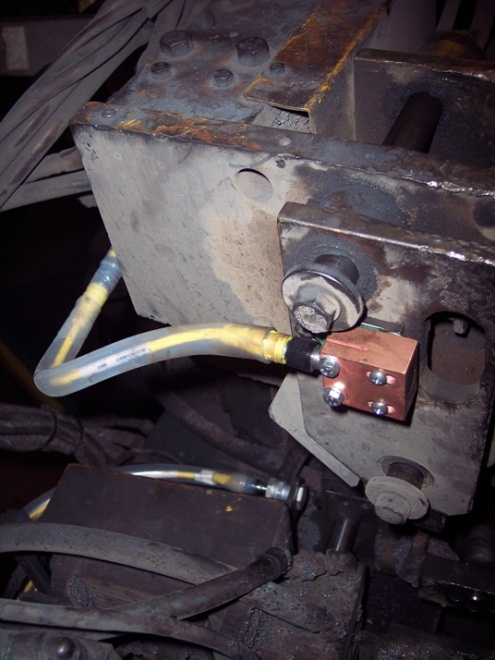
In the current era of steel production, steel manufacturers employ a continuous process during the casting phase of production. The molten steel is solidified during this process by a continuous casting machine. The processes include feeding the liquid steel through a series of rollers to cool the material and slowly form into the next shape of production (e.g. slabs, round, etc…). In this process, the rollers are positioned using hydraulic cylinders that include linear position sensors as closed loop feedback devices. The outputs of these sensors are closely monitored and are critical to the steel quality. Because of the harsh environment of the continuous casting process, the life span of these sensors can be cut short. If the sensor’s output becomes unstable and begins to fail, the continuous casting process cannot simply stop quickly. The steel quality during this sensor failure mode will most likely become scrap, costing the steel mill tens of thousands of dollars.

btl7-t-redundant-series
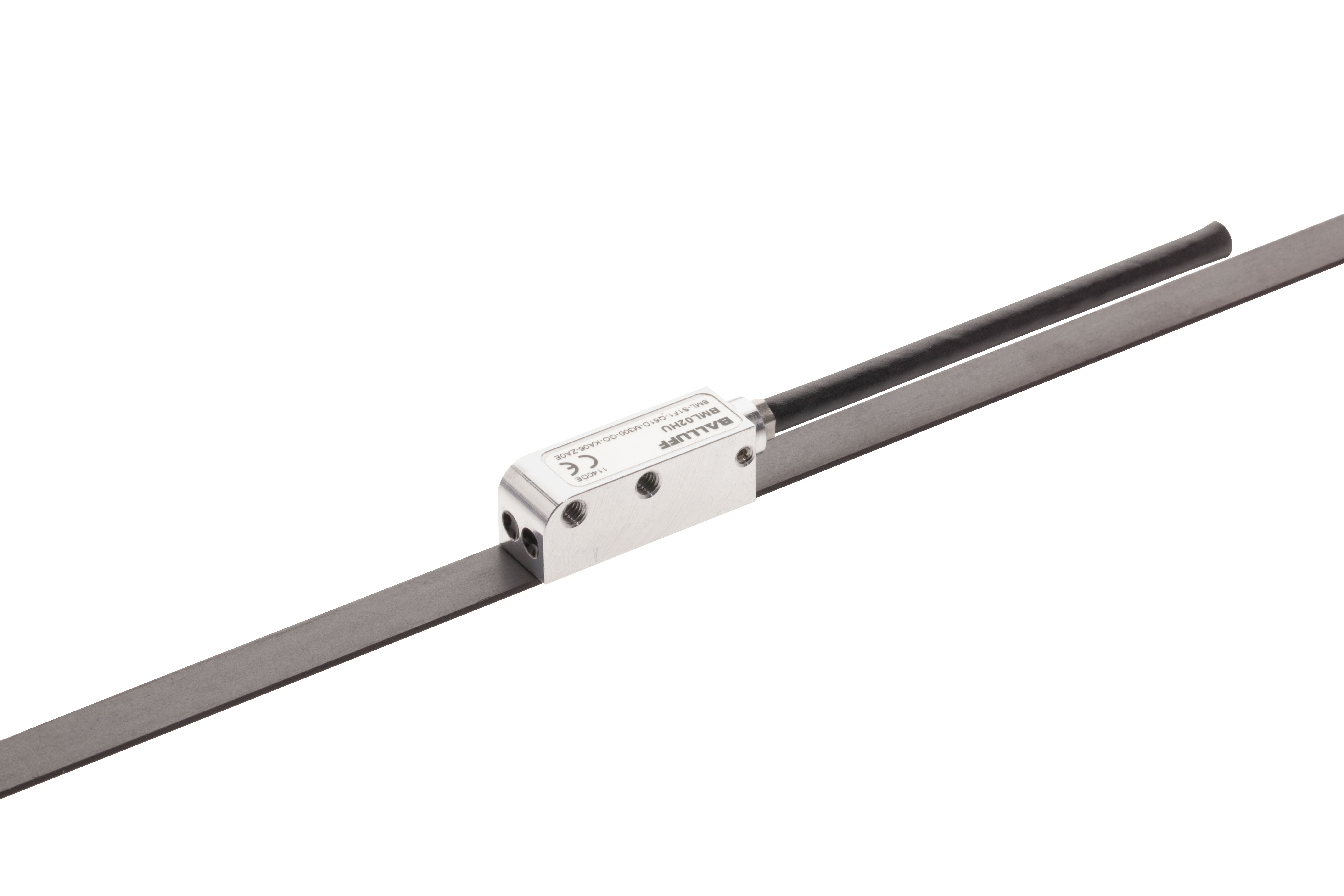
For maximum reliability, a linear position sensor with 2 or 3 times redundancy can be utilized to provide position feedback of hydraulic systems. Such sensors employ 2 or 3 independently-operating sensing elements and processing circuitry . The extra feedback signals can be monitored through an automation system. When the outputs are compared, a failure could be identified early and the automation system could switch over to the reliable output maintaining the quality of steel. No scrap! During the next possible scheduled stoppage in the manufacturing process, the sensor could be replaced.

For more information on Balluff solutions for the metallurgy industry, start here.

For more information, visit www.balluff.com.

Reliable Part Exit/Part-Out Detection

Walk into any die shop in the US and nine out of ten times, we discover diffuse reflective sensors being used to detect a large part or a small part exiting a die. Many people have success using this methodology, but lubrication-covered tumbling parts can create challenges for diffuse-reflective photoelectric sensing devices for many reasons:

  1. Tumbling parts with many “openings” on the part itself can cause a miss-detected component.
  2. Overly-reflective parts can false triggering of the output.
  3. Dark segments of the exiting part can cause light absorption. Remember, a diffuse sensors sensing distance is based on reflectivity. Black or dark targets tend to absorb light and not reflect light back to the receiver.
  4. Die lube/misting can often fog over a photoelectric lens requiring maintenance or machine down time.

The solution: Super Long Range Inductive Sensors placed under chutes

Most metal forming personnel are very familiar with smaller versions of inductive proximity sensors in tubular sizes ranging from 3mm through 30mm in diameter and with square or “block style” inductive types (flat packs, “pancake types”, etc.) but it is surprising how many people are just now discovering “Super Long Range Inductive Proximity” types. Super Long Range Inductive Proximity Sensors have been used in metal detection applications for many years including Body-In-White Automotive applications, various segments of steel processing and manufacturing, the canning industry, and conveyance.

Benefits of Using A UHMW Chute + Super Long Range Inductive Proximity Sensor in Part Exit/Part-Out Applications:

  1. It is stronger and quieter than parts flowing over a metal chute, readily available in standard and custom widths, lengths and thicknesses to fit the needs of large and small part stampers everywhere.
  2. UHMW is reported to be 3X stronger than carbon steel.
  3. UHMW is resistant to die lubes.
  4. UHMW allows Super Long Range Inductive Proximity Sensors to be placed underneath and to be “tuned” to fit the exact zone dimension required to detect any part exiting the die (fixed ranges and tunable with a potentiometer). The sensing device is also always out of harm’s way.
  5. Provides an option for part detection in exiting applications that eliminates potential problems experienced in certain metal forming applications where photoelectric sensing solutions aren’t performing optimally.
A Two-Out Die with Metallic Chute

Not every Part Exit/Part-Out application is the same and not every die, stamping application, vintage of equipment, budget for sensing programs are the same. But it’s important to remember in the world of stamping, to try as consistently as possible to think application specificity when using sensors.  That is, putting the right sensing system in the right place to get the job done and to have as many technical options available as possible to solve application needs in your own “real world” metal forming operation.  We believe the UHMW + Super Long Range Inductive System is such an option.

You can learn more in the video below or by visiting www.balluff.us.

Putting Linear Encoders Out of Sight and Out of Mind

Linear encoders can do a lot to improve factory automation. When used as secondary feedback they can greatly enhance the precision of motion control systems. They can act as a feedback device for automatic size change, and they can be used in gauging applications.

However, they can be troublesome to maintain. Most linear encoders are made from a glass strip or rod that is etched with index marks and read optically. These kinds of encoders can achieve very high accuracy…with high price points to match. However, a consistent problem in many factory automation environments is the mechanical fragility of the glass scale encoder. They can be easily broken by shock, vibration, or impact. The presence of dirt and liquids can also interfere with proper operation. Repair costs can become a problem, not to mention the cost of carrying the spare parts needed to cope with long lead times for replacements.

bml-s1fDepending on the resolution and accuracy class required, one alternative to these issues is the magnetic linear encoder. Today’s magnetic encoders can achieve resolution to 1 μm and accuracy to ±5 μm. Rather than index marks on glass, the scale consists of magnetic poles precisely located on a ferromagnetic strip of tape. A magnetic read head glides over the tape and outputs digital position signals. The magnetic system is much more tolerant of shock and vibration, and can tolerate most kinds of liquids and dirt. The main caveat is ferrous particles or chips; these can accumulate on the magnetic strip and cause position deviations.

Most magnetic linear encoders offer incremental signals, but a new option is absolute position over an SSI or BiSS-C serial interface. This allows the encoder to report position upon power-up, without the need for a time-wasting homing or reference run. This can be helpful in situations like a power outage, where it may not be possible to re-home the machine without damaging work in process and/or breaking tooling.

To learn more visit www.balluff.us.

Angle Sensing & Tilt Detection Solutions

When an application calls for angle sensing or tilt detection there are a few choices including fluid based and MEMS technology Inclination sensors. For this blog entry we will focus on the MEMS technology. MEMS offerings have the option of one or two axis with up to 360° of measuring range. They provide an easy means of directly detecting positions without making contact enabling continuous feedback of rotational movements along the axis. The precise position control and continuous positioning of rotational movements are critical in many applications making them reliable solutions where accurate positioning is a must.

Sensors based with the MEMS technology operate by taking a capacitance differential and converting it to an analog signal. This analog signal is relative to the angle of the sensor in the application. The compact housing sizes are also a great feature offering various mounting options for a wide range of applications.

constructionequipmentMEMS Inclinations sensors can be used in various types of applications. Inclination sensor typically have  robust IP67 ratings making them ideal for tilt protection for cranes, hoists, tractors, expandable mechanical arms and other types of mobile agricultural machines. The Inclination sensor controls and monitors efficient operation verifying the correct positioning needed for reliable operation.

It is not uncommon to see MEMS style inclination offerings used in the renewable energy market. You can commonly see applications where inclination sensors are mounted directly to a rotating shaft to provide angel feedback for Fresnel Solar Panels.

inclinationsensorProduct Features:

  • Compact housing
  • Low temperature drift
  • Contact Free operation
  • High repeat accuracy
  • Precise analog measurement
  • Shock resistant

Applications:

  • Cranes
  • Hoist/Boom Trucks
  • Lifts
  • Mobile Implements
  • Shaft rotation
  • Solar Power

For more information on inclination sensors visit www.balluff.us.

3 Tips for Reducing Downtime

Whether it’s through preventative maintenance or during planned machine downtime, reducing downtime is a common goal for manufacturers. Difficult environments create challenges for not just machines, but also the components like sensors or cables. Below are three tips to help protect these components and reduce your downtime.

sacraficialcableCables don’t last forever. However, they are important for operations and keeping them functional is vital. An easy way to help reduce downtime and save money is by implementing a “sacrificial cable” in unforgiving environments. A sacrificial cable is any cable less than two meters in length and placed in situations where there is high turnover of cables.  This sacrificial cable does not have to be a specialty cable with a custom jacket. It can be a simple 1 meter PVC cable that will get changed out often. The idea is to place a sacrificial cable in a problematic area and connect it to a longer length cable, or a home-run cable. The benefits of this method include: less downtime for maintenance when changing out failures, reduced expenses since shorter cables are less expensive, and there is less travel for the cable around a cell.

hdc_cablesA second way to help reduce downtime is consider your application conditions up front. We discussed some of the application conditions to consider in a previous blog post, but how can we address these challenges? Not only is it important to choose the correct sensor for the environment, but remember, cables don’t last forever. Choosing the appropriate cable is also key to reducing downtime. Welding environments demand a cable that weld beads will not stick to and fuse the cable to the sensor. There are a variety of jacket types like silicone, silicone tube, or PTFE that prevent weld debris from accumulating on the cable. I’ve also seen applications where there is a lot of debris cutting through cables. In this case, a stainless steel braid cable would be a better solution than a traditional cable. Fitting the right protection to the right application is crucial..

gizmo4A third tip to help reduce your machine downtime is to simply add protection to your existing components. Adding protection, whether it is a protective bracket or a silicone product, will help keep components running longer. This type of protection can be added before or after the cell is operational.   One example of sensor protection is adding a ceramic cap to protect the face of a sensor. You can also protect the connection by adding tubing to the cable out version of the sensor to shield it from debris. Mounting sensors in a robust bracket helps protect the sensor from being hit, or having debris cover the sensor.  There are different degrees of changes that help prolong operations.

Metalforming expert, Dave Bird, explains some of these solutions in the video below. To learn more you can also visit our website at www.balluff.us.


Identification technology for Work In Process applications is evolving

wipI have had countless conversations over the years regarding barcode vs RFID. Most of those discussions I explained that both technologies have their own unique set of features and benefits and it is rarely the case where they are competing. I still stand by that general argument except when it applies to Work In Process applications. Looking back over the last four to six years there is evidence of a major evolution from barcode to RFID in the production process.

I guess the next question is why is this happening? I am not sure I have the definite answer, but there are a couple consistent factors that tend to come up when we are installing RFID in place of barcode:

Automation – True automation means there are no manual processes. When an operator has to pull a trigger on a barcode scanner the scan is not automated. Even with fixed barcode readers the barcode will sometimes need to be presented to the reader by an operator holding the part. With fixed RFID scanners the part is automatically scanned even without a direct line of sight and even in poor lighting conditions.

ROI – At first glance a barcode solution may seem to be more cost effective than RFID. However, things that need to be taken into account when going the barcode route are: specialized lighting, data management, longevity of the barcode in a harsh environment, etc. With RFID the tags can be read in complete darkness, the data can be managed locally, and the tags are built to survive harsh conditions. In addition, the cost of paper RFID labels has become manageable in the last couple years.

This is definitely something I will be keeping my eye on going forward. With a renewed focus on automation, identification technology will become more and more important as we move toward true automation.

To learn more about industrial RFID systems visit www.balluff.us.

Solar tracking systems and sensors

Over the last few years there has been a lot of discussion on how we will meet the global energy demand in the future. And what will be the technologies to generate it? In the end it all comes down to the levelized cost of electricity (LCOE), which is the sum of all costs of a power plant divided by the total electricity that is generated over the plant’s lifetime. All companies in the renewable energy industry focus on reaching lower LCOE compared to conventional power generation (especially gas). Their biggest advantage is that there are no costs for fuel (sun light, wind, water).

solarpanelsLet’s take solar power as an example. Principally there are two ways to use the sun light: First it can be converted directly to electricity (photovoltaics). Second, it can be used indirectly by generating thermal energy (concentrated solar power). In order to reach higher efficiency solar trackers are used to orient photovoltaic panels, reflectors, or mirror towards the sun. On the other hand they add costs to the system. Therefore it must be carefully calculated whether a tracker (single or dual axis) is required or not (fixed installation).

solarpanels2Single axis trackers are used to position photovoltaic panels, parabolic troughs or linear Fresnel collectors from east to west on a north to south orientation. Depending on the required tracking accuracy different sensors are used for this task. As most of the photovoltaic trackers use electric linear actuators, very often inductive sensors are installed on the actuator for position feedback. They are cost optimized and are a standard feature in the actuators. Another option is to use inclination sensors that are directly mounted on the rotating shaft to provide angle feedback (e.g. in linear Fresnel plants). As inclinometers are mounted on the moving part, there is cable wear that could lead to failure over time. For high end tracking, as is required in parabolic trough plants, magnetic tape systems are used as rotary encoders. A magnetic tape is mounted around the shaft and a sensor head is installed on the frame of the tracker. The sensor counts the pulses accurately and provides continuous position feedback without any wear.

solarpanels3Dual axis trackers are used to position concentrated photovoltaic (CPV) panels, parabolic reflectors (dish) or mirrors (heliostats). Especially in central receiver plants high accuracy is required. They need high temperatures and therefore have to focus lots of light on a central receiver on top of a tower in the middle of the heliostat field. As there is an azimuth and an elevation axis, two position feedback systems are required. The elevation angle could be solved with an inclinometer, but this does not work for the azimuth position.  Again, the position could be measured with embedded rotary encoders directly on the drive. But there is again backlash, and accuracy is of highest importance as heliostats could be one mile away from the central receiver. Magnetically coded position and angle measurement systems can be mounted on both axis (azimuth and elevation) and provide direct position feedback with highest accuracy.

More information can be found in this brochure about power generation. http://asset.balluff.com/std.lang.all/pdf/binary/861522_162563_1305_en-US.pdf

Special thank you to Bernd Schneider, Industry Manger – Balluff GmbH for contributing to this post.

JSON Objects and How They Can Streamline an IIoT Application

In web development, JSON objects are a programmer’s dream come true. JSON, or JavaScript Object Notation, is much similar to XML (EXtensible Markup Language) in that it’s used as a standard format to organize and transfer data across multiple programming languages. For example, say you want to send sensor data from a SQL database to a JavaScript front end. JavaScript doesn’t know SQL syntax and SQL doesn’t know JavaScript syntax. How do these different languages communicate? JSON/XML will act as a middle ground between the two allowing them to talk to each other. When given a choice between the two, I’m always going to pick JSON objects as they are much more efficient than XML. They are shorter in length and easier for computers and people to interpret. Here’s what 3 sensors would look like in XML versus JSON:

xml
Example of XML
json
Example of JSON

dpropHow does this apply to the Industrial Internet of Things? The JSON format for data transfer is so universal that IO-Link modules host it on a web server. This server is accessible by entering the IP address of the module. The module data can be seen in JSON format by modifying the IP address and adding “/dprop.jsn” into the URL of a web browser (i.e. 192.168.0.1/dprop.jsn). You should see something similar to the image on the right.

reqqresarchThe “dprop” stands for data propagation or simply the movement of data from one source to multiple sources. This data is delivered with a standard request-response system. Say you’re writing some software that uses the sensor data as variables. All that’s needed to get that sensor data is a few lines of code that send a request to the module which in turn responds with your data.

opcuaHow does this differ from the Industrial Internet of Things (IIoT) application frameworks from my past blogs? Previously, we discussed using OPC UA software to subscribe to PLC data and forwarding this data to a SQL database. From there, the application would query SQL for the data and render it appropriately for the user experience. Using JSON objects, we entirely eliminate the need for SQL or OPC UA software by accessing the data directly from the module. This not only makes the application independent from the PLC but also uses much less network traffic. However, using JSON objects, we can only subscribe to data from IO Link devices.

All acronyms aside, there are a million different ways to structure an IIoT application. The best fitting architecture depends on the environment. Systems with standard input/output will most likely need some form of communication with the controller. IO-Link systems will streamline this process by allowing the user to directly access the module’s IO Link data. How you go about building your application is entirely up to you. In the end, however, having this information readily available via the Industrial Internet of Things will be more beneficial than you could have ever imagined.

To learn more about IIoT visit www.balluff.us.

Demand the Best from Your RFID Partner

RFIDThat seems like a no-brainer statement, but often I find myself talking to customers who are frustrated with their current vendor for a myriad of reasons. An RFID project can require a pretty decent chunk of capital investment so when something doesn’t go as planned people start looking for answers immediately. This usually presents a great opportunity for us to go in and save the day, but it’s hard for me to ignore the time, money and resources that were wasted. Having witnessed this on several occasions I have concluded that there are a large number of RFID companies who are niche suppliers, but there are very few who can qualify as an RFID Partner. The RFID partner helps ensure success from idea to implementation to future expansion. That said, here is a list of things to consider prior to discussing your application with an RFID company:

  • Does the partner offer hardware that communicates over USB, Serial, TCP/IP, Ethernet/IP, Profinet/Profibus, CC-Link, Ethercat, etc?
  • Does the partner offer a wide range of form factors of readers, tags, and antennae?
  • Does the partner build hardware for multiple frequencies?
  • Is the partner willing to build custom equipment just right for your application?
  • Does the partner offer support before, during and after the project?
  • Does the partner have a core competency in the application?
  • Can the partner meet application specs such as, high temperatures, high speed reading on the fly, storing and reading large amounts of data, high ingress protection rating, etc.?
  • Does the partner develop and design products which are scalable and easily expandable?

If you can answer yes to all of these questions then chances are you are pretty well set. With such a mature technology there are many ways for RFID companies to set themselves apart from one another. However, there are only a few who are willing to do what it takes to be considered a partner.

To learn more about RFID technology visit www.balluff.us/rfid

Linear Measurement Sensors for Short Stroke Applications

We’ve posted numerous articles here on the Sensortech blog about linear position sensors used for applications such as hydraulic cylinder position feedback, plastic injection molding machinery, tire manufacturing machinery, etc.  What all of the applications have in common is that we’re generally talking about fairly long linear travels, usually longer than 12″, sometimes up to 300″.spindle

But in applications such as spindle clamp positioning on machine tools or positioning of
linear movements on automated assembly machinery, travels are sometimes only a couple of inches, and the available space to mount a position sensor is extremely limited.  Fortunately, there are highly capable linear position sensors that are perfectly suited for such applications.

For example, there are sensors that use an array of inductive coils to detect the bips
precise linear position of a simple metal target.  These sensors, with working strokes ranging from < 1″ up to around 5″ have are extremely compact, with very little dead zone.  That means they fit into very tight spaces, where other type of linear position sensors simply couldn’t.

Typically, these types of sensors provide a position signal in the form of an analog voltage (0-10V) or current (4-20 mA).  Increasingly though, IO-Link interfaces are gaining in popularity, offering simplified wiring, better noise immunity, built-in diagnostics, and the ability to easily get the position data into virtually any industrial field-bus architecture.

For more information, visit www.balluff.com