Inductive coupling – simple concept for complex automation

Inductive coupling is not new to automation. The concept in various forms has been around for over few decades. It was not actively used, and my guess is that more than form factor or functionality of couplers, it has to do with automation technology relying on mechanical and hard wired components. With growing complexity and ever evolving technology, the inductive coupling has also evolved.  Nowadays, you can charge your smart phones or tablets using the charging pad that uses the very same technology.

power&dataexchange
Figure 1: Inductive coupling for power and data exchange

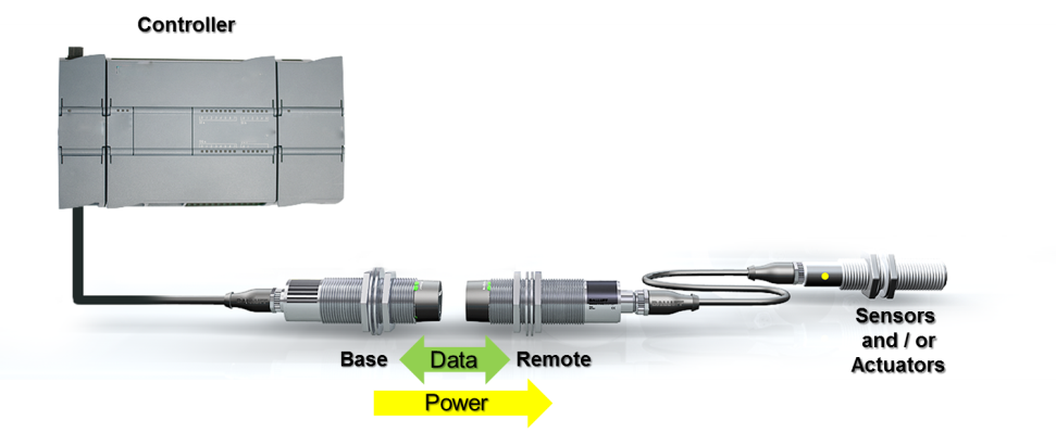
In industrial automation space, inductive sensors are very popular and commonly used for detecting proximity of metal objects such as food cans, or machine parts. Inductive coupling uses magnetic induction to transfer power and data over an air gap. Yes, it is a kind of very short range wireless technology that also enables power transfer.

SlipRing
Figure 2: Slip ring example

In this series of blogs on inductive coupling, we can explore various use cases of inductive coupling in complex automation. Today, let’s see how inductive coupling compares with traditional slip-ring mechanism.

Slip-rings, also known as rotary connectors, are typically used in areas of the machine where one part rotates and other part of the machine remains stationary. For example, an indexing table or turn table where stations on the indexing table need power and I/O but the table rotates through full 360°, hence standard cable solutions are ineffective. A slip ring could be installed at the base of the table.

ReplacingSlipRing
Figure 3: Inductive coupling replacing the slip-ring

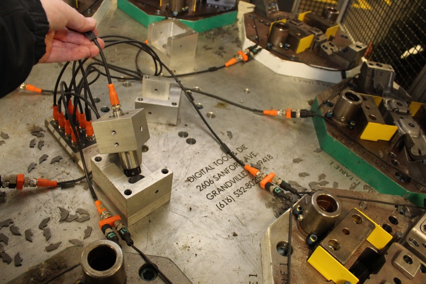
Since, slip rings are electromechanical devices, in the long term they are subject to wearing out. Unfortunately, the signs of wear are not evident unless one day there is no power to the table. An inductive coupling solution eliminates all the hassle of the mechanical parts. With non-contact inductive coupling, the base coupler could be mounted at the base of the table and the remote coupler could be mounted on the rotating part of the table. Slip rings are susceptible to noise and vibration because they are electromechanical devices, whereas inductive couplers are not because there is no contact between the base and the remote.  In fact, the turn table shown above uses an inductive coupler.

Inductive coupler, typically have IP67 rating for the housing are not affected by dirt or water, are immune to vibrations, and most important they are contact free so no maintenance is required unless you hammer one out. Learn more about Balluff inductive couplers: www.balluff.us.

When to use IO-Link RFID

IO-Link logoAt this point it is pretty clear that RFID is a fairly simple identification solution that involves a tag, antenna, and processor. The tag holds the information that is critical to the application. That information could be a very brief identifying number, sometimes called a license plate, and usually consists of 4 to 12 Bytes of data. Or, the application may require the tag to hold all the information about the product being manufactured such as build data, process data, or lineage data. In this case, there are tags with up to 128 Kilobytes of available storage. The scenarios above help to answer the question: “when do I use IO-Link RFID?”

Simply put, IO-Link makes life on the manufacturing floor much easier. It eliminates the mess in the cabinet, it is plug and play, it allows connection to any major controller, etc. etc. etc. So, why not just do away with everything not IO-Link and call it a day? For RFID there is 1 major question that needs to be answered to determine whether or not IO-Link is the right solution: How much data needs to be read from the tag?

IO-link specializes in transferring smaller amounts of data. When required to transfer large amounts the speed is greatly reduced. Here is a very simple way to look at it: IO-Link RFID comes in two different versions- 10Bytes or 32Bytes. The 10 Bytes or 32 Bytes refer to the size of the buffer or container that transfers the data. Imagine this as two semi-trucks carrying a load in a trailer (buffer). Of course, the 32 Byte trailer can carry a larger load (Data) than the 10Byte trailer. Therefore, we can conclude that the 10Byte trailer has to make more trips to carry larger amounts of data. More trips take more time therefore slowing down the process. If there are only 8Bytes of data that need to be read from the tag then the 10Byte version is fine, but if there are 28 bytes then it makes sense to us the 32 Byte version. However, as mentioned above there are applications where the tag may hold up to 8KB, 32KB, or even 128KB of data and IO-Link should not be considered. As a general rule IO-link should not be used to read anything over 96 Bytes due to speed being greatly reduced.

Need For Speed?

As a rule of thumb it takes about .2 seconds for IO-Link RFID readers to read 16Bytes of data and about .5 seconds to read 96Bytes. Reading anything above 96Bytes increases the read time dramatically. As a comparison, the latest and greatest Balluff RFID processor, the BIS V can read 256Bytes of data in about .2 seconds.

Ultimately, the amount of data that needs to be read from the tag and the time required to read that data should be the deciding factors of whether or not IO-Link RFID is right for the job or not.

To learn more about IO-Link visit www.balluff.us

5 Tips on Making End-of-Arm Tooling Smarter

Example of a Flexible EOA Tool with 8 sensors connected with an Inductive Coupling System.

Over the years I’ve interviewed many customers regarding End-Of-Arm (EOA) tooling. Most of the improvements revolve around making the EOA tooling smarter. Smarter tools mean more reliability, faster change out and more in-tool error proofing.

#5: Go Analog…in flexible manufacturing environments, discrete information just does not provide an adequate solution. Analog sensors can change set points based on the product currently being manufactured.

#4: Lose the weight…look at the connectors and cables. M8 and M5 connectorized sensors and cables are readily available. Use field installable connectors to help keep cable runs as short as possible. We see too many long cables simply bundled up.

#3: Go Small…use miniature, precision sensors that do not require separate amplifiers. These miniature sensors not only cut down on size but also have increased precision. With these sensors, you’ll know if a part is not completely seated in the gripper.

#2: Monitor those pneumatic cylinders…monitoring air pressure in one way, but as speeds increase and size is reduced, you really need to know cylinder end of travel position. The best technology for EOA tooling is magnetoresistive such as Balluff’s BMF line. Avoid hall-effects and definitely avoid reed switches. Also, consider dual sensor styles such as Balluff’s V-Twin line.

#1: Go with Couplers…with interchangeable tooling, sensors should be connected with a solid-state, inductive coupling system such as Balluff’s Inductive Coupler (BIC). Avoid the use of pin-based connector systems for low power sensors. They create reliability problems over time.

Consider this when using multi-vendor IO-Link solutions

The IO-Link consortium allows for multiple master connections from DIN rail slice IP20 solutions to IP67 ports.  As usage of IO-Link has grown dramatically over the last two years and adoption of multi-vendor solutions continues to rise, there will be a point where you may encounter an alternate type of IO-Link connection for IP67 masters and devices in the market.

The specification allows for a wide variety of connectors and conductors for the IO-Link master/slave connection specifically calling out M5, M8 & M12 connectors.  The default port and pin configuration for an IO-Link master port is the M12 A-coded connection with port type A.  In IO-Link port A, the power for the IO-Link slave device is provided entirely by the pins 1&3 similar to a standard proximity sensor according to IEC 61076-2-101.  This is the most common port type in use today and is found on the widest variety of sensors and slave devices.

An alternate port type is available, IO-Link Port B, to provide galvanically isolated power to the IO-Link slave device.  In this configuration a second power supply can be added for isolated control power.  It is not widely adapted in IO-Link slave devices today but can be found in some products where this is an application requirement.  If a master or device has a port type B it must be clearly labelled on the product per the specification.

PortAPortB

If there is not a port type identified on the device then it is assumed to be a port A type device as it is the default configuration.  Balluff IO-Link masters and devices are mostly of the type port A.  Check out Balluff’s IO-Link offering.


1 Visual Way to Improve Operator Performace

Many manufacturers I talk to are excited about the possibilities that our new Smart Light technology, used in level mode, brings to their production or machines.  Here’s a video if you havent seen it yet:

It works over virtually any industrial network with an open standard called IO-Link, which I’ve discussed many times in previous posts.

What I’m really impressed with is the number of people integrating the level mode as a quick and easy way to give instantaneous feedback to an operator on their performance to a quota or as a count-down timer.  Here you can see in the middle of the right photo a bright green bar light just to the left of the red kanban rack.  There are multiple of these lights in this image.

Tesla Motors Blog – Factory Upgrade

This light is a five zone Smart Light operating in level mode.  As the cycle time winds down, the light decreases in value until there is no more time, at that point it flashes bright red to notify the operator to cycle to the next vehicle.  It keeps the production on track and helps operators know quickly and easily how much time remains.  What I’ve been told is nice about this is how bright the light is and that it is easily install-able without a controls cabinet or slice i/o j-box like you can see in the photo.  Others like it because it makes the data visual from all over, where HMIs require you to stand right in front of them for information.

So if you are trying to think about ways to visualize data in your process or production to operators or managers, there are many others out there already using Smart Light for that application. Check it out.

Rise of the Robots – 3 Ways to Be On Their Team

While originally a mixed reviewed 1994 console video game, the recently published report by The Boston Consulting Group titled “The Rise of Robotics”  really made me realize how important it is that we embrace robotics in our manufacturing processes.  And I strongly agree with this statement: “Because robots can sharply improve productivity and offset regional differences in labor costs and availability, they’ll likely have a major impact on the competitiveness of companies and countries alike.”  They studied the growth of the usage of robots in personal, commercial, military and industrial use and the numbers were quite powerful.  Of interest to me is the rise in industrial robotics; doubling in 5 years from $5.8b to $11.0b in 2015.  And the growth is expected to more than double again by 2025 to $24.4b in the industrial space.

What this means for manufacturers, machine builders and component suppliers is we need to make sure our people are trained to support this growth and that we we have strong peripheral technologies to support robots as they grow and expand.  Even today there are some great technologies available in sensors and controls that make robotic integration easier for manufacturing companies.

So here are the three ways to make sure you are your robot’s ally.

  1. Maximize Their Payload!

    No one wants to be treated like they can’t help… especially your robots, they want you to utilize them and feel appreciated.  For most robotics right now, payload size & payload weight is a limiting factor.  Mini sensing products with precision switch points, small form factors and low mass allow for the design of low weight, compact payloads without limiting the functionality or speed of the robot.

  2. Keep them Working!

    A working robot is a happy robot.  By adding flexible tooling or quick-change tooling to the end-effector of a robot you can have one arm perform multiple functions and keep idle arms to a minimum, increasing their value and “happiness.”  Multiple products are out there to allow for this, however there is a technology that allows for sensor connections through inductive coupling that dramatically decreases repair issues and downtime due to tool changer pins.

  3. Remove the Chains!  

    What’s the deal with cable dress packs… they look like really bad suspenders sometimes… you see them, you don’t like how they look, but you need it to keep your pants on… I guarantee that robots don’t like these things either… And with all that flexing something in there will fail regularly.  There are some great technologies to reduce the sensor cables running on the arm and add flexibility and they are supported by the open standard IO-Link (discussed in other posts here!).

So as you integrate robots more and more into the manufacturing we are doing, please start thinking how to align yourself as a robot’s ally.  Because I know I want to be on this guy’s team…

The iphone is for more than Angry Birds… Apps for Engineers

Recently I came across this link on control engineering’s website and I just had to share it.  They have created an app that organizes and summarizes all the available useful apps for an engineer on the go.  From Autocad/Solidworks reference tools to basics on engineering topics to standards document references they have collected the perfect library for you to find the tools you need and maybe didn’t know existed.  And in the long run I think the goal is to make us more productive, even when sitting in baggage claim waiting for our toolbox.  As for me, I can’t wait until April when I can trade in my blackberry and get my iphone to give this app a spin.

Take a look at their offering, let me know what you think.  What apps are you using today for your designs?  What apps do you wish were out there for engineers?  Which apps should I download first?

Position Monitoring with EtherCAT

Much has been written here on SensorTech about the value of industrial networking in the machine automation realm.  As the trend towards industrial networking continues to expand, we see more and more network-capable sensors coming to the fore.  Linear position sensors are no exception.

Network-connected linear position sensors take the concept of continuous, absolute linear position feedback a step or two forward by allowing the position sensor to be directly connected to the network, and also providing additional information in the form of sensor-level diagnostics.

Two such examples of network-connected linear position sensors are the newly introduced Micropulse EtherCAT position transducers.

Available in two varieties, one for basic position monitoring, and one capable of closed-loop positioning tasks, the Micropulse EtherCAT transducer is a good example of the continuing evolution of basic sensors towards more “intelligent” network-capable sensors.

For more information on industrial networking products, start here.

Stop Industrial Network Failures With One Simple Change

Picture1

It’s the worst when a network goes down on a piece of equipment.  No diagnostics are available to help troubleshooting and all communication is dead.  The only way to find the problem is to physically and visually inspect the hardware on the network until you can find the culprit.  Many manufacturers have told me over the past few months about experiences they’ve had with down networks and how a simple cable or connector is to blame for hours of downtime.

2013-08-19_Balluff-IO-Link_Mexico_Manufactura-de-Autopartes_healywBy utilizing IO-Link, which has been discussed in these earlier blogs, and by changing the physical routing of the network hardware, you can now eliminate the loss of communication.  The expandable architecture of IO-Link allows the master to communicate over the industrial network and be mounted in a “worry-free” zone away from any hostile environments.  Then the IO-Link device is mounted in the hostile environment like a weld cell and it is exposed to the slag debris and damage.  If the IO-Link device fails due to damage, the network remains connected and the IO-Link master reports detailed diagnostics on the failure and which device to replace.  This can dramatically reduce the amount of time production is down.  In addition the IO-Link device utilizes a simple sensor cable for communication and can use protection devices designed for these types of cables.  The best part of this is that the network keeps communicating the whole time.

If you are interested in learning more about the benefits that IO-Link can provide to manufacturers visit www.balluff.us.

Sacrificing for the Greater Good

Environments with debris and caustic agents, wear down equipment exponentially. When a cell goes down, every minute counts to get production up and running.  An accessory like a cordset is important for operations, and can frustrate technicians when it fails. Cordsets do not last forever in this environment and to help save money, time and work, we came up with the concept of a “sacrificial cable.” The basic idea is to install a double-ended cable under 2 meters to help in situations where cables are placed in surroundings which will destroy the cable.  A sacrificial cable’s main function is to save time reducing cable replacement downtime and money.

Sacrifice Cordset Solution: Used in extremely rugged applications to reduce cordset replacement downtime

hrcable

A sacrificial cable does not have to be a specialty cable with a custom jacket; it could just be a 1 meter PVC cable that will get changed out often. The idea is that by placing a sacrificial cable in a problematic area and connecting it to a longer length cable this will allow maintenance to have a shorter down time when changing out failures less.  This is accomplished with travel around the cell following a cable run and less maintenance expense in labor.

Continue reading “Sacrificing for the Greater Good”