Inductive Sensors and Their Unlimited Uses in Automation

Inductive sensors (also known as proximity sensors or proxes) are the most commonly used sensors in mechanical engineering and industrial automation. When they were invented in the 1960s, they marked a milestone in the development of control systems. In a nutshell, they generate an electromagnetic field that reacts to metal targets that approach the sensor head. They even work in harsh environments and can solve versatile applications.

There are hardly any industrial machines that work without inductive sensors. So, what can be solved with one, two, three, or more of them?

What can you do with one inductive sensor?

Inductive sensors are often used to detect an end position. This could be in a machine for end-of-travel detection, but also in a hydraulic cylinder or a linear direct drive as an end-of-stroke sensor. In machine control, they detect many positions and trigger other events. Another application is speed monitoring with a tooth wheel.

What can you do with two inductive sensors?

By just adding one more sensor you can get the direction of rotational motion and take the place of a more expensive encoder. In a case where you have a start and end position, this can also be solved with a second inductive sensor.

What can you do with three inductive sensors?

In case of the tooth wheel application, the third sensor can provide a reference signal and the solution turns into a multiturn rotary encoder.

What can I do with four inductive sensors and more?

For multi-point positioning, it may make sense to switch to a measurement solution, which can also be inductive. Beyond that, an array of inductive sensors can solve identification applications: In an array of 2 by 2 sensors, there are already 16 different unique combinations of holes in a hole plate. In an array of 3 by 3, it would be 512 combinations.

Control Meets IIoT, Providing Insights into a New World

In manufacturing and automation control, the programmable logic controller (PLC) is an essential tool. And since the PLC is integrated into the machine already, it’s understandable that you might see the PLC as all that you need to do anything in automation on the manufacturing floor.

Condition monitoring in machine automation

For example, process or condition monitoring is emerging as an important automation feature that can help ensure that machines are running smoothly. This can be done by monitoring motor or mechanical vibration, temperature or pressure. You can also add functionality for a machine or line configuration or setup by adding sensors to verify fixture locations for machine configuration at changeovers.

One way to do this is to wire these sensors to the PLC and modify its code and use it as an all-in-one device. After all, it’s on the machine already. But there’s a definite downside to using a PLC this way. Its processing power is limited, and there are limits to the number of additional processes and functions it can run. Why risk possible complications that could impact the reliability of your control systems? There are alternatives.

External monitoring and support processes

Consider using more flexible platforms, such as an edge gateway, Linux, and IO-Link. These external sources open a whole new world of alternatives that provide better reliability and more options for today and the future. It also makes it easier to access and integrate condition monitoring and configuration data into enterprise IT/OT (information technology/operational technology) systems, which PLCs are not well suited to interface with, if they can be integrated at all.

Here are some practical examples of this type of augmented or add-on/retrofit functionality:

      • Motor or pump vibration condition monitoring
      • Support-process related pressure, vibration and temperature monitoring
      • Monitoring of product or process flow
      • Portable battery based/cloud condition monitoring
      • Mold and Die cloud-based cycle/usage monitoring
      • Product changeover, operator guidance system
      • Automatic inventory monitoring warehouse system

Using external systems for these additional functions means you can readily take advantage of the ever-widening availability of more powerful computing systems and the simple connectivity and networking of smart sensors and transducers. Augmenting and improving your control systems with external monitoring and support processes is one of the notable benefits of employing Industrial Internet of Things (IIoT) and Industry 4.0 tools.

The ease of with which you can integrate these systems into IT/OT systems, even including cloud-based access, can dramatically change what is now available for process information-gathering and monitoring and augment processes without touching or effecting the rudimentary control system of new or existing machines or lines. In many cases, external systems can even be added at lower price points than PLC modification, which means they can be more easily justified for their ROI and functionality.

IO-Link Benefits in Robotic Weld Cell Tooling

By Scott Barhorst

Working previously as a controls engineering manager in robotic welding, I have seen some consistent challenges when designing robotic weld cell systems.

For example, the pre-engineered-style welding cells I’ve worked with use many types of tooling. At the same time, space for tooling and cabling is limited, and so is the automation on board, with some using PLC function and others using a robot controller to process data.

One approach that worked well was to use IO-Link in the systems I designed. With its simple open fieldbus communication interface and digital transmission, it brought a number of benefits.

    1.  IO-Link’s digital signals aren’t affected by noise, so I could use smart sensors and connect them with unshielded 4-pin cables.
    2.  Expandability was easy, either from the Master block or by adding discrete I/O modules.
    3.  IO-Link can use the ID of the block to identify the fixture it is associated with to make sure the correct fixture is in the correct location.
    4.  Cabling is simplified with IO-Link, since the IO-Link Master can control both inputs, outputs, and control valve packs. That means that the only cables needed will be 24V power, Ethernet, weld ground (depending on the system), and air.
    5.  Fewer cables means less cost for cables and installation, cable management is improved, and there are fewer cables to run through a tailstock or turntable access hole.

One system I designed used 1 IO-Link Master block, 3 discrete I/O modules, and 1 SMC valve manifold controlled via IO-Link. This tooling had 16 clamps and 10 sensors, requiring 42 total inputs and control of 16 valves. The system worked very well with this setup!

An additional note: It’s good to think beyond the process at hand to how it might be used in the future. A system built on IO-Link is much more adaptable to different tooling when a change-over is needed. Click here to read more about how to use IO-Link in welding environments.


IO-Link: End to Analog Sensors

With most sensors now coming out with an IO-Link output, could this mean the end of using traditional analog sensors? IO-Link is the first IO technology standard (IEC 61131-9) for communications between sensors and actuators on the lower component level.

Analog sensors

A typical analog sensor detects an external parameter, such as pressure, sound or temperature, and provides an analog voltage or current output that is proportional to its measurement. The output values are then sent out of the measuring sensor to an analog card, which reads in the samples of the measurements and converts them to a digital binary representation which a PLC/controller can use. At both ends of the conversion, on the sensor side and the analog card side, however, the quality of the transmitted value can be affected. Unfortunately, noise and electrical interferences can affect the analog signals coming out of the sensor, degrading it over the long cable run. The longer the cable, the more prone to interference on the signal. Therefore, it’s always recommended to use shielded cables between the output of the analog sensor to the analog card for the conversion. The cable must be properly shielded and grounded, so no ground loops get induced.

Also, keep in mind the resolution on the analog card. The resolution is the number of bits the card uses to digitalize the analog samples it’s getting from the sensor. There are different analog cards that provide 10-, 12-, 14-, and 16-bit value representations of the analog signal. The more digital bits represented, the more precise the measurement value.

IO-Link sensor—less interference, less expensive and more diagnostic data

With IO-Link as the sensor output, the digital conversion happens at the sensor level, before transmission. The measured signal gets fed into the onboard IO-Link chipset on the sensor where it is converted to a digital output. The digital output signal is then sent via IO-Link directly to a gateway, with an IO-Link master chipset ready to receive the data. This is done using a standard, unshielded sensor cable, which is less expensive than equivalent shielded cables. And, now the resolution of the sensor is no longer dependent on the analog card. Since the conversion to digital happens on the sensor itself, the actual engineering units of the measured value is sent directly to the IO-Link master chipset of the gateway where it can be read directly from the PLC/controller.

Plus, any parameters and diagnostics information from the sensor can also be sent along that same IO-Link signal.

So, while analog sensors will never completely disappear on older networks, IO-Link provides good reasons for their use in newer networks and machines.

To learn about the variety of IO-Link measurement sensors available, read the Automation Insights post about ways measurement sensors solve common application challenges. For more information about IO-Link and measurement sensors, visit www.balluff.com.

Controls Architectures Enable Condition Monitoring Throughout the Production Floor

In a previous blog post we covered some basics about condition monitoring and the capability of smart IO-Link end-devices to provide details about the health of the system. For example, a change in vibration level could mean a failure is near.

This post will detail three different architecture choices that enable condition monitoring to add efficiency to machines, processes, and systems: in-process, stand-alone, and hybrid models.

IO-Link is the technology that enables all three of these architectures. As a quick introduction, IO-Link is a data communications technology at the device level, instead of a traditional signal communication. Because it communicates using data instead of signals, it provides richer details from sensors and other end devices. (For more on IO-Link, search the blog.)

In-process condition monitoring architecture

In some systems, the PLC or machine controller is the central unit for processing data from all of the devices associated with the machine or system, synthesizing the data with the context, and then communicating information to higher-level systems, such as SCADA systems.

The data collected from devices is used primarily for controls purposes and secondarily to collect contextual information about the health of the system/machine and of the process. For example, on an assembly line, an IO-Link photo-eye sensor provides parts presence detection for process control, as well as vibration and inclination change detection information for condition monitoring.

With an in-process architecture, you can add dedicated condition monitoring sensors. For example, a vibration sensor or pressure sensor that does not have any bearings on the process can be connected and made part of the same architecture.

The advantage of an in-process architecture for condition monitoring is that both pieces of information (process information and condition monitoring information) can be collected at the same time and conveyed through a uniform messaging schema to higher-level SCADA systems to keep temporal data together. If properly stored, this information could be used later for machine improvements or machine learning purposes.

There are two key disadvantages with this type of architecture.

First, you can’t easily scale this system up. To add additional sensors for condition monitoring, you also need to alter and validate the machine controller program to incorporate changes in the controls architecture. This programming could become time consuming and costly due to the downtime related to the upgrades.

Second, machine controllers or PLCs are primarily designed for the purposes of machine control. Burdening these devices with data collection and dissemination could increase overall cost of the machine/system. If you are working with machine builders, you would need to validate their ability to offer systems that are capable of communicating with higher-level systems and Information Technology systems.

Stand-alone condition monitoring architecture

Stand-alone architectures, also known as add-on systems for condition monitoring, do not require a controller. In their simplest form, an IO-Link master, power supply, and appropriate condition monitoring sensors are all that you need. This approach is most prevalent at manufacturing plants that do not want to disturb the existing controls systems but want to add the ability to monitor key system parameters. To collect data, this architecture relies on Edge gateways, local storage, or remote (cloud) storage systems.


The biggest advantage of this system is that it is separate from the controls system and is scalable and modular, so it is not confined by the capabilities of the PLC or the machine controller.

This architecture uses industrial-grade gateways to interface directly with information technology systems. As needs differ from machine to machine and from company to company as to what rate to collect the data, where to store the data, and when to issue alerts, the biggest challenge is to find the right partner who can integrate IT/OT systems. They also need to maintain your IT data-handling policies.

This stand-alone approach allows you to create various dashboards and alerting mechanisms that offer flexibility and increased productivity. For example, based on certain configurable conditions, the system can send email or text messages to defined groups, such as maintenance or line supervisors. You can set up priorities and manage severities, using concise, modular dashboards to give you visibility of the entire plant. Scaling up the system by adding gateways and sensors, if it is designed properly, could be easy to do.

Since this architecture is independent of the machine controls, and typically not all machines in the plant come from the same machine builders, this architecture allows you to collect uniform condition monitoring data from various systems throughout the plant. This is the main reason that stand-alone architecture is more sought after than in-process architecture.

It is important to mention here that not all of the IO-Link gateways (masters) available in the market are capable of communicating directly with the higher-level IT system.

Hybrid architectures for condition monitoring

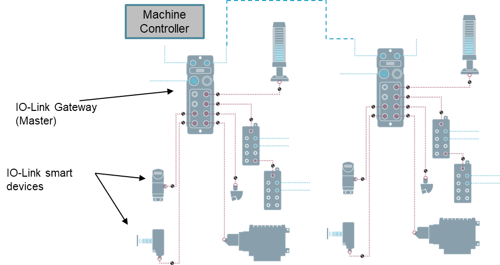
As the name suggests, this approach offers a combination of in-process and stand-alone approaches. It uses IO-Link gateways in the PLC or machine controller-based controls architecture to communicate directly with higher-level systems to collect data for condition monitoring. Again, as in stand-alone systems, not all IO-Link gateways are capable of communicating directly with higher-level systems for data collection.

The biggest advantage of this system is that it does not burden PLCs or machine controllers with data collection. It creates a parallel path for health monitoring while devices are being used for process control. This could help you avoid duplication of devices.

When the devices are used in the controls loop for machine control, scalability is limited. By specifying IO-Link gateways and devices that can support higher-level communication abilities, you can add out-of-process condition monitoring and achieve uniformity in data collection throughout the plant even though the machines are from various machine builders.

Overall, no matter what approach is the best fit for your situation, condition monitoring can provide many efficiencies in the plant.

What is IO-Link? A Simple Explanation of the Universal Networking Standard

Famed physicist Albert Einstein once said, “If you can’t explain it simply, you don’t understand it well enough.” When the topic of IO-Link comes up, whether a salesperson or technical expert is doing the explaining, I always find it’s too much for the layman without a technical background to understand. To simplify this complex idea, I’ve created an analogy to something we use in our everyday lives: highways.  

Prior to the Federal Highway Act of 1956, each individual state, determined the rules of its state highway routes. This included everything from the width of the roads to the speed limits and the height of bridge underpasses — every aspect of the highways that were around at the time. This made long-distance travel and interstate commerce very difficult. It wasn’t until 1956 and the passage of President Eisenhower’s Federal Highway Act, that the rules became standard across the entire United States. Today, whether you’re in Houston, Boston or St. Louis, everything from the signage on the road to the speed limits and road markings are all the same. 

Like the standardization of national highway system, the IO-Link Consortium standardized the rules by which devices in automation communicate. Imagine your home as a controller, for example, the roads are cables, and your destination is a sensor. Driving your car to the store is analogous to a data packet traveling between the sensor and the controller.  

You follow the rules of the road, driving with a license and abiding by the speed limits, etc. Whether you’re driving a sedan, an SUV or a semitruck, you know you can reach your destination regardless of the state it’s in. IO-Link allows you to have different automation components from different suppliers, all communicating in sync unlike before, following a standard set of rules. This empowers the end user to craft a solution that fits his or her needs using sensors that communicate using the protocols set by the IO-Link Consortium. 

Improve OEE, Save Costs with Condition Monitoring Data

When it comes to IIOT (Industrial Internet of Things) and the fourth industrial revolution, data has become exponentially more important to the way we automate machines and processes within a production plant. There are many different types of data, with the most common being process data. Depending on the device or sensor, process data may be as simple as the status of discrete inputs or outputs but can be as complex as the data coming from radio frequency identification (RFID) data carriers (tags). Nevertheless, process data has been there since the beginning of the third industrial revolution and the beginning of the use of programmable logic controllers for machine or process control.

With new advances in technology, sensors used for machine control are becoming smarter, smaller, more capable, and more affordable. This enables manufacturers of those devices to include additional data essential for IIOT and Industry 4.0 applications. The latest type of data manufacturers are outputting from their devices is known as condition monitoring data.

Today, smart devices can replace an entire system by having all of the hardware necessary to collect and process data, thus outputting relative information directly to the PLC or machine controller needed to monitor the condition of assets without the use of specialized hardware and software, and eliminating the need for costly service contracts and being tied to one specific vendor.

A photo-electric laser distance sensor with condition monitoring has the capability to provide more than distance measurements, including vibration detection. Vibration can be associated with loose mechanical mounting of the sensor or possible mechanical issues with the machine that the sensor is mounted. That same laser distance sensor can also provide you with inclination angle measurement to help with the installation of the sensor or help detect when there’s a problem, such as when someone or something bumps the sensor out of alignment. What about ambient data, such as humidity? This could help detect or monitor for moisture ingress. Ambient pressure? It can be used to monitor the performance of fans or the condition of the filter elements on electrical enclosures.

Having access to condition monitoring data can help OEMs improve sensing capabilities of their machines, differentiating themselves from their competition. It can also help end users by providing them with real time monitoring of their assets; improving overall equipment efficiency and better predicting  and, thereby, eliminating unscheduled and costly machine downtime. These are just a few examples of the possibilities, and as market needs change, manufacturers of these devices can adapt to the market needs with new and improved functions, all thanks to smart device architecture.

Integrating smart devices to your control architecture

The most robust, cost effective, and reliable way of collecting this data is via the IO-Link communication protocol; the first internationally accepted open, vendor neutral, industrial bi-directional communications protocol that complies with IEC61131-9 standards. From there, this information can be directly passed to your machine controller, such as PLC, via fieldbus communication protocols, such as EtherNET/Ip, ProfiNET or EtherCAT, and to your SCADA / GUI applications via OPC/UA or JSON. There are also instances where wireless communications are used for special applications where devices are placed in hard to reach places using Bluetooth or WLAN.

In the fast paced ever changing world of industrial automation, condition monitoring data collection is increasingly more important. This data can be used in predictive maintenance measures to prevent costly and unscheduled downtime by monitoring vibration, inclination, and ambient data to help you stay ahead of the game.

Rise of the Robots: IO-Link Maximizes Utilization, Saves Time and Money

Manufacturers around the world are buying industrial robots at an incredible pace. In the April 2020 report from Tractia & Statista, “the global market for robots is expected to grow at a compound annual growth rate (CAGR) of around 26 percent to reach just under 210 billion US dollars by 2025.” But are we gaining everything we can to capitalize on this investment when the robots are applied? Robot utilization is a key metric for realizing return-on-investment (ROI). By adding smart devices on and around the robot, we can improve efficiencies, add flexibility, and expand visibility in our robot implementations. To maximize robot utilization and secure a real ROI there are key actions to follow beyond only enabling a robot; these are: embracing the open automation standard IO-Link, implementing smart grippers, and expanding end-effector application possibilities.

In this blog, I will discuss the benefits of implementing IO-Link. Future blog posts will concentrate on the other actions.

Why care about IO-Link?

First, a quick definition. IO-Link is an open standard (IEC 61131-9) that is more than ten years old and supported by close to 300 component suppliers in manufacturing, providing more than 70 automation technologies (figure 1). It works in a point-to-point architecture utilizing a central master with sub-devices that connect directly to the master, very similar to the way USB works in the PC environment. It was designed to be easy to integrate, simple to support, and fast to implement into manufacturing processes.

Figure 1 – The IO-Link consortium has close to 300 companies providing more than 70 automation technologies.

Using standard cordsets and 24Vdc power, IO-Link has been applied as a retrofit on current machines and designed into the newest robotic work cells. Available devices include pneumatic valve manifolds, grippers, smart sensors, I/O hubs, safety I/O, vacuum generators and more. Machine builders and equipment OEMs find that IO-Link saves them dramatically on engineering, building and the commissioning of new machines. Manufacturers find value in the flexibility and diagnostic capabilities of the devices, making it easier to troubleshoot problems and recover more quickly from downtime. With the ability to pre-program device parameters, troublesome complex-device setup can be automated, reducing new machine build times and reducing part replacement times during device failure on the production line.

Capture Data & Control Automation

Figure 2 – With IIoT-ready IO-Link sensors and masters, data can be captured without impacting the automation control.

The final point of value for robotic smart manufacturing is that IO-Link is set up to support applications for the Industrial Internet of Things (IIoT). IO-Link devices are IIoT ready, enabling Industry 4.0 projects and smart factory applications. This is important as predictive maintenance and big-data applications are only possible if we have the capabilities of collecting data from devices in, around and close to the production. As we look to gain more visibility into our processes, the ability to reach deep into your production systems will provide major new insights. By integrating IIoT-ready IO-Link devices into robotic automation applications, we can capture data for future analytics projects while not interrupting the control of the automation processes (figure 2).

Tire Manufacturing – IO-Link is on a Roll

Everyone working in the mobility industry knows that the tire manufacturing process is divided up into five areas throughout a large manufacturing plant.

    1. Mixing
    2. Tire prep
    3. Tire build
    4. Curing and molds
    5. Final inspection

Naturally,  conveyors, material handling, and AGV processes throughout the whole plant.

All of these areas have opportunities for IO-Link components, and there are already some good success stories for some of these processes using IO-Link.

A major opportunity for IO-Link can be found in the curing press area. Typically, a manufacturing plant will have about 75 – 100 dual cavity curing presses, with larger plants having  even more. On these tire curing presses are many inputs and outputs in analog signals. These signals can be comprised of pressure switches, sensors, pneumatic, hydraulic, linear positioning, sensors in safety devices, thermo-couples and RTD, flow and much more.

IO-Link provides the opportunity to have all of those inputs, outputs and analog devices connected directly to an IO-Link master block and hub topography. This makes it not only easier to integrate all of those devices but allows you to easily integrate them into your PLC controls.

Machine builders in this space who have already integrated IO-Linked have discovered how much easier it is to lay out their machine designs, commission the machines, and decrease their costs on machine build time and installations.

Tire manufacturing plants will find that the visual diagnostics on the IO-Link masters and hubs, as well as alarms and bits in their HMIs, will quickly help them troubleshoot device problems. This decreases machine downtime and delivers predictive maintenance capabilities.

Recently a global tire manufacturer getting ready to design the curing presses for a new plant examined the benefits of installing IO-Link and revealed a cost savings of more than $10,000 per press. This opened their eyes to evaluating IO-Link technology even more.

Tire Manufacturing is a perfect environment to present IO-Link products. Many tire plants are looking to upgrade old machines and add new processes, ideal conditions for IO-Link. And all industries are interested in ways to stretch their budget.


How to Take Advantage of IO-Link Parameter Data

IO-Link data packets contain parameter data of an IO-Link slave device that is acyclic and is only transferred when read or write is requested by the machine controller. Having parameter data available on a device is not new or groundbreaking; however, the main advantage of IO-Link parameter data is that it is directly accessible by the machine controller, and it is dynamic, meaning you do not have to take the device offline to change its parameters or configuration. Parameter data determines how flexible or configurable an IO-Link slave device is. Its content will be different from device to device and manufacturer to manufacturer, a differentiator when choosing the right device for your application. We all know that not all IO-Link devices are created equal.

So how can you take advantage of parameter data?

Automatic machine configuration

Imagine if your machine could automatically configure itself upon first power-up? Yes, it is possible. Because IO-Link parameter data is accessible by the machine controller, i.e., the PLC or PAC, one can write a routine/program that first verifies the correct device is connected to the correct port of the IO-Link master, request a parameter read, compare the parameter content to the desired configuration in the program, and overwrite the current device parameter set if necessary. Why would someone do this? Well, if you are an OEM machine builder building ten of the same machines for one end customer, it would be a worthwhile investment in programming development to have IO-Link devices configured automatically. This method would eliminate the need for manual machine parameterization and result in cost savings. Examples of typical configuration would be changing the pin assignment of an IO-Link freely configurable discrete input/output hub as an input or an output, machine home position or offset of an IO-Link linear transducer, set points of an IO-Link pressure transducer, set points of an IO-Link laser distance sensor, and so on.

Recipe change

Another way to take advantage of IO-Link parameter data is to have the machine controller automatically change device configuration based on recipe change. This would eliminate the need for an operator to manually change device parameters, thus saving time and minimizing human error, especially if the device is not easily accessible by a human.

Maintenance

Having direct access to device parameters by the machine controller also enables OEMs to simplify their machines’ serviceability. For component replacement, all the maintenance personnel would have to replace a damaged device with a new device and walk away, eliminating the need for specialized training, software, or hardware.

Some manufacturers add special functions to their IO-Link masters to enable automatic backup and restoration of IO-Link slave device parameters, making replacement of components as easy as plug and play. This function would eliminate the need for OEMs to create custom programs or logic in their PLCs to restore parameter sets on a device automatically.

How to

So how would I do this? Because parameter data is accessible by the machine controller, implementation of auto configuration differs based on what brand of controller you are using. I will mention a few of the most popular.

  • Allen Bradley – For the Allen Bradley family of PLCs, you would use an explicit  instruction to read and write IO-Link device parameters.
  • Siemens -For the Siemens family of PLCs, you would use a standard function block named “FB_IOL_CALL”.

As you can see, every PLC or machine controller manufacturer and their flavor of IDE (Integrated Development Environment) will have their unique way of accessing IO-Link device parameter set. It is best to consult with both manufacturers and review IO-Link devices and PLCs to better understand how to set the read and write parameters of an IO-Link slave device.

Conclusion

Having direct access to device parameters and being able to change them without taking the device offline or needing special software or hardware, and implement it at a device level is game-changing. It opens doors for time and cost savings in design, integration, operation, and serviceability of machines. It is different from what we are used to, so don’t be afraid to think outside of the box and jump in with both feet.