
The complexity of factory automation creates constant challenges which drive innovation in the industry. One of these challenges involves the ability to accurately detect the presence of shiny or highly reflective objects. This is a common challenge faced in a variety of applications, from sensing wheels in an automotive facility to detecting an aluminum can for filling purposes at a beverage plant. However, thanks to advancements in photoelectric sensing technologies, there is a reliable solution for those type of applications.
Why are highly reflective objects a challenge?
Light reflects from these types of objects in different directions, and with minimum energy loss. This can cause the receiver of a photoelectric sensor to be unable to differentiate between a signal received from the emitter or a signal received from a shiny object. In the case of a diffuse sensor, there is also the possibility that when trying to detect a shiny object, the light will reflect away from the receiver causing the sensor to ignore the target.
So how do we control the direction of the light going back to the receiver, and avoid false triggering from other light sources? The answer is in polarized retroreflective sensors.
Retroreflective sensors require a reflector which reflects the light back to the sensor allowing it to be captured by the receiver. This is achieved by incorporating sets of three mirrors oriented at right angles from each other (referred to as corner cubes). A light beam entering this system is reflected by all three surfaces and exits parallel to the incident beam. Additionally, corner cubes are said to be optically active as they rotate the plane of oscillation of the light by 90 degrees. This concept, along with polarization, allow this type of sensor to accurately detect shiny objects.
Polarization
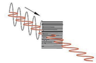
Light emitted by a regular light source oscillates in planes on dispersal axes. If the light meets a polarizing filter (fine line grid), only the light oscillating parallel to the grid is let through (see figure 1 below).
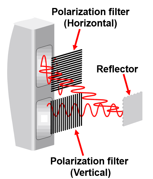
In polarized retroreflective sensors, a horizontal polarized filter is placed in front of the emitter and a vertical one in front of the receiver. By doing this, the transmitted light oscillates horizontally until it hits the reflector. The corner cubes of the reflector would then rotate the polarization direction by 90 degrees and reflect the light back to the sensor. This way, the returning light can pass through the vertical polarized filter on the receiver as shown below.
With the use of polarization and corner cubed reflectors, retroreflective sensors can create a closed light circuit which ensures that light detected by the receiver was sourced exclusively by the emitter. This creates a great solution for applications where highly reflective targets are influencing the accuracy of sensors or causing them to malfunction. By ensuring proper operation of photoelectric sensors, unplanned downtime can be avoided, and overall process efficiency can be improved.
