
Did you ever wonder how an Inductive Proximity Sensor is able to detect the presence of a metallic target? While the underlying electrical engineering is sophisticated, the basic principle of operation is not too hard to understand.
At the heart of an Inductive Proximity Sensor (“prox” “sensor” or “prox sensor” for short) is an electronic oscillator consisting of an inductive coil made of numerous turns of very fine copper wire, a capacitor for storing electrical charge, and an energy source to provide electrical excitation. The size of the inductive coil and the capacitor are matched to produce a self-sustaining sine wave oscillation at a fixed frequency. The coil and the capacitor act like two electrical springs with a weight hung between them, constantly pushing electrons back and forth between each other. Electrical energy is fed into the circuit to initiate and sustain the oscillation. Without sustaining energy, the oscillation would collapse due to the small power losses from the electrical resistance of the thin copper wire in the coil and other parasitic losses.
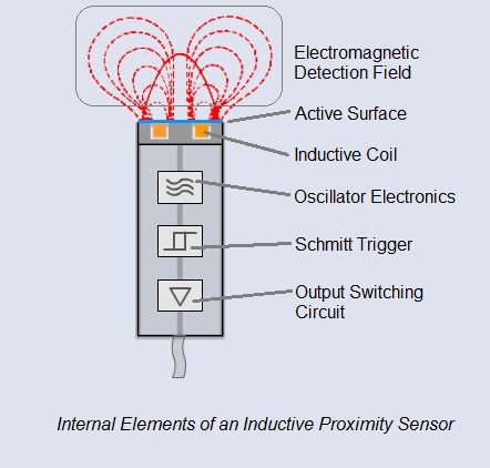
The oscillation produces an electromagnetic field in front of the sensor, because the coil is located right behind the “face” of the sensor. The technical name of the sensor face is “active surface”.
When a piece of conductive metal enters the zone defined by the boundaries of the electromagnetic field, some of the energy of oscillation is transferred into the metal of the target. This transferred energy appears as tiny circulating electrical currents called eddy currents. This is why inductive proxes are sometimes called eddy current sensors.
The flowing eddy currents encounter electrical resistance as they try to circulate. This creates a small amount of power loss in the form of heat (just like a little electric heater). The power loss is not entirely replaced by the sensor’s internal energy source, so the amplitude (the level or intensity) of the sensor’s oscillation decreases. Eventually, the oscillation diminishes to the point that another internal circuit called a Schmitt Trigger detects that the level has fallen below a pre-determined threshold. 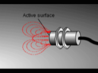 This threshold is the level where the presence of a metal target is definitely confirmed. Upon detection of the target by the Schmitt Trigger, the sensor’s output is switched on.
The short animation to the right shows the effect of a metal target on the sensor’s oscillating magnetic field. When you see the cable coming out of the sensor turn red, it means that metal was detected and the sensor has been switched on. When the target goes away, you can see that the oscillation returns to its maximum level and the sensor’s output is switched back off.
Want to learn more about the basic operating principles of Inductive Proximity Sensors? Here’s a short YouTube video covering the basics:

Well explained. This will be of great help especially to instrumentation students.
That’s great to hear! Sounds like an excellent program of study.
I really appreciate the explanations on inductive and capacitive sensors.
We’re glad to hear it! Thank you for the nice feedback.
Nice Blog..thanks for giving the information.
Data Trace Automation
You’re welcome! We’re glad you found it interesting.
Thank you! Can you explain the operation of a capacitive proximity sensor?
Thanks for your interest. You can visit this post to learn more about the physical principles of capacitive sensors.
Is it possible to get the inductance variation in the inductive coil instead of getting a trigger signal? To not only detect the metal but also measure the distance between it and the sensor.
Thank you
Great question. Yes, it is possible for an inductive sensor to be designed with a continually variable output signal that is proportional to the damping state of the oscillator. This can be used to detect distance to target, as you mentioned, and also to differentiate between different metallurgies, such as between steel, aluminum, brass, and copper.
This type of sensor is called an analog inductive distance sensor. Typical output signals are 0-10V DC, 4-20mA, and serial digital data over IO-Link.
Designing a top-performing analog inductive distance sensor requires a lot of engineering experience, skill, knowledge, and testing. The primary design challenge is to deliver a high-resolution, high accuracy output with excellent linearity and high position stability as the ambient temperature changes (low temperature drift).
Here are some examples of analog inductive distance sensors.
Great explanation! I have found it very useful. I would like to share a problem I have been having with certain sensors and I have not been able to find a solution nor an explanation to this matter.
I have an inductive sensor connected to a 24 VDC power supply and I receive the detection signal through a PLC. The problem is sometimes the sensor is triggered by the presence of a metal and remains triggered even though the metal has been removed from the active surface for a long period of time, maybe even minutes. What could be the problem?
I use these sensors as an automation system for hydraulic cylinders and I can’t withstand wrong signals, due to certain restrictions built from these sensors. Any ideas?
Thank you, Daniel and you raise a good point for discussion. Regarding your issue of a sensor remaining triggered after the target has been removed: this condition is called “latching on”. It can occur when the sensor remains “damped” enough to hold the sensor in the “on” condition. To understand how a sensor could stay on after the target is removed, we need to talk about the property of “hysteresis”.
Every inductive proximity sensor inherently has some degree of hysteresis. Hysteresis is necessary for the sensor to operate in a stable manner, so that it doesn’t rapidly “chatter” or switch on/off rapidly close to the switching point. Hysteresis, basically, is the distance between the switch-on point and the switch-off point when the target is moving away from the active surface. Typical values are stated in sensor data sheets; common values would be ≤ 15%, ≤ 10%, ≤ 5% and so on. The value is taken as a % of the actual switch-on distance of the individual sensor specimen. Generally, the higher the % of hysteresis, the more stable the sensor is and the farther away the target must move to turn off the sensor.
Some factors that could cause “latching on” behavior:
• Using a quasi-flush, non-flush, or extended-range sensor that is too close to metal surrounding its sides. If there is a lot of metal close to the sides of the sensor, a flush-type sensor may eliminate the latching-on problem (although it will have shorter range). What’s happening is that the metal is partially damping the sensor. While not enough to turn the sensor on, it is enough to hold it in the on state due to hysteresis.
• Having the mounting nuts too close to the face of a quasi-flush, non-flush, or extended-range sensor. Even though there are threads in that area, the mounting nuts can pre-damp the sensor.
• Using a sensor that is not very stable at higher temperatures. Some sensors are more susceptible to latching-on than others as temperature is increased. This is caused by temperature drift, which can increase the sensor’s sensitivity to metals. In these cases, the sensor may work fine at start-up or at room temperature, but as the machinery gets hot it will start latching on. The solution is to make sure that the sensor is rated for the ambient temperature in the application. Another option: look for sensors designed properly by a reputable manufacturer and/or look for sensors specifically designed to work at higher temperatures.
• Strong magnetic fields can cause standard inductive proximity sensors to latch on. This happens because the magnetic field oversaturates the coil, so that the sensor is unable to detect that the target has been removed. If this is the case, replace them with “weld field immune” or “weld field tolerant” sensors.
• For simple end-of-stroke cylinder applications, built-in pressure-rated inductive sensors are ideal. These must be ordered at the time of cylinder manufacturing because the cylinder must be designed to accept them.
• For applications where the sensors must be adjusted to different positions, consider upgrading to continuous position feedback with a profile-type magnetostrictive linear position sensor. These types of linear position sensors can be retrofitted to existing hydraulic cylinder applications. For new cylinders, internally-mounted rod-style linear position sensors can be installed.
For more information about proximity sensor switching distances and hysteresis, please take a look at this related blog post.
Thank you very much for the information. It has been very useful. I have one last question. Can this “latching-on” situation be caused by the power source? All my sensors are connected to the same 24 VDC power source. Its rated power is 240W. I have a total of 55 sensors connected, but the sensors are not the only load the power source feeds. I have other analog sensors, as well as PLCs, signal modules, valves, etc. The power consumption for inductive sensors is very low so I guess my power source is clearly overrated. However, some technician told me this problem could be related to the power source. I don’t think so. Can this be possible?
Daniel, some sensors can operate between 10-30 VDC while others require 24 VDC +/- 10% for example. If there is excessive load on the power supply, it would appear as low bus voltage, i.e. something less than 24 VDC. Unless it drops below 10 VDC, the 10-30 VDC sensors will not be affected. If it drops below 20-21 VDC then standard 24V sensors may become unstable in their operation. You could use a multimeter to check the voltage across the Blue and Brown leads at the sensor.
If the sensor is giving a high signal, is it possible to place and object in front of the sensor to make it switch off. I have an application where induction sensor is not switching off sometimes because there is metal about 10mm away. sensor is rated for 8mm.
John, this is likely a case of the sensor exhibiting hysteresis. The switch-off point is further away from the face of the sensor than the switch-on point. This is an intentional design feature to prevent sensor instability when a target is passing through the turn-on point. We would not want the sensor to jitter on and off as the target approaches, so once the sensor turns on, it stays on until the target backs away a certain distance. Please check out this related blog post for more information about sensor switching characteristics. Just by chance, I analyzed a sensor with an 8mm rated operating distance. The worst-case turn off point would be about 10.6mm.
Is it possible to use a timer in the inductive sensor for the high side and relay for the low side or vice versa? Since I cannot use a relay only for multiple connections of the inductive sensor, it will result in failure during testing. By the way, we are monitoring a metal carrier for the carousel and we are placing the sensor in multiple locations to detect any breakage on the carrier.
Relay and timing logic can get rather complicated and difficult to troubleshoot when going beyond more than two sensors. The best approach is to use a small, inexpensive PLC as the basis for system control. This allows flexible programming of the machine function and status monitoring.
Can I use an inductive proximity sensor as a switch, to turn on and off the power? If yes, how?
Typically, inductive proximity sensors are classified as pilot devices. They are intended to provide pilot signals to a controller, which then signals outputs to turn on and off to control other devices. In some very simple systems with low power requirements, an inductive prox can directly operate small electrical loads like LED lights or small DC solenoids. If AC loads or DC loads with higher power demands are to be controlled, typically an electro-mechanical relay is needed. The sensor operates the relay, and the relay operates the load.
Thank you very much! I don’t know what is the output of the inductive proximity sensor: is it the same voltage and current as input, or it bit lower because accordingly I have to find the
relay.
You’re welcome! In the case of a typical 24V DC 3-wire sensor, the output voltage is the same as the supply voltage, minus a very small amount of voltage drop across the sensor, which can usually be ignored. The output current from the sensor to the driven load depends on the continuous operating current rating of the sensor, which is given in the sensor data sheet. Most 3-wire DC inductive sensors have continuous current ratings in the 100 to 200mA DC range.
Thank you; this is helpful. I found a DC relay that works with my 3-wire DC sensor, which is rated for 80mA continuous current. I have a follow-up question: can I connect a load (an electromagnet) which draws 2A @ 24V DC, to the same power supply as the sensor?
Glad to hear you’re making progress. Yes, you can use the same power supply for the sensor and the relay. Just be sure that the power supply has enough extra current capacity to supply the inrush current of the load without triggering the short-circuit protection or blowing a fuse on the power supply. Also, if the power supply’s current capacity is too low, the short circuit may not trigger but the output voltage may drop below 24V…which might cause the sensor to switch off and/or the relay to chatter.
Can you explain how a capacitive sensor operates?
Thanks for your question, Jade. Jack Moermond and Bjoern Schaefer have described the operation of a capacitive sensor in this blog post: https://sensortech.wordpress.com/2010/06/10/part-ii-capacitive-sensors/
I am working on a thesis involving methods of sorting materials in a refuse recycling machine. How can I employ inductive and capacitive technologies to automatically separate wet, dry, plastic, and metal objects? Thank you for any suggestions.
Thank you for posting, Jade. Mixed material sorting is a rather complex and challenging task. Machines that do this are highly engineered and specialized, and often employ patented approaches. But speaking generally, capacitive sensors are used to detect non-metallic objects and inductive sensors are used to detect metallic objects. One approach to the challenge of mixed material sorting could be to first detect and separate the metals using inductive sensors, and then evaluate the remaining materials using capacitive sensors. In both cases, the degree of discrimination between different kinds of metals and different kinds of non-metals could be enhanced by using analog sensors. Analog sensors deliver variable signals in response to targets, based on the degree of sensor activation by the target size and material. These signals can be evaluated by logical systems to determine the nature of the target material under examination.
Hi, Would like to know how to put this to use in a metallic punching machine to detect missing metallic parts in a closed conveyor and connect to the machine’s emergency stop and halt the stoppage too?
Inductive proximity sensors are ideal for detection tasks in metal stamping and punching operations. Generally speaking, the larger the sensing distance, the larger the coil size needs to be to get enough detection range. More precise sensing tasks demand smaller proxes with more precise switching characteristics. There are many locations where inductive sensors can be applied: double-blank detection, in-feed confirmation, in-die detection, slug-out confirmation, and part-out confirmation. In some cases optical or photoelectric sensors can be applied as well.
Integration of part status sensors into the press control is a job for a controls engineer. There are several variables to be considered depending on the particular application and equipment in use. You might try contacting a local press automation specialist for an in-plant consultation.
When it comes to selecting and applying sensors in the stamping industry, Balluff’s metalforming expert Dave Bird shares his practical insights in a series of videos here: https://www.youtube.com/playlist?list=PLDn-3vmBD0chUFs-k_u5ioLY9YqTTRFkD
Sir, can you show the circuit of an inductive proximity sensor?
The actual electrical circuit of an inductive sensor is rather complicated, often involving ASICs (Application-Specific Integrated Circuits), and the circuits are typically the proprietary intellectual property of the manufacturer.
We can provide a block diagram that shows the major functional elements of an inductive proximity sensor:
If I understand correctly, you indicate that the extra power of the Joules heat loss due to Eddy currents when there is a metal target in front of the sensor is, some how, a noticeable extra cost “taken” from the power of the sensor’s oscillator circuit (which by such will lose power).
The sensor is emitting an alternative magnetic field. You are suggesting that according to the use of this magnetic field power by a potential target (no metal target = no power used, on a metal target = power loss by Joules heating), the sensor’s oscillator circuit will “know” of this use and will spend more or less power?
I’m not sure of this. In my opinion, it is the inducted magnetic field generated by the Eddy currents (Biot Savart law) that is sensed by specific coil in the sensor.
The sensor generated alternative magnetic field is not affected by the way its emitted power is being used.
Essentially, there is air-gap transformer coupling between the sensor coil (primary) and the metal target (secondary). The secondary of the “transformer” is a short circuit in the steel target, hence the eddy currents circulate “uselessly”. In so circulating, they create power losses in the form of resistive heating. This energy for generating heat must come from somewhere…and it can come only from the oscillator circuit. The effective “Q” factor of the oscillator is thus reduced; as more energy is consumed in the target, less energy is stored in the oscillator. The efficiency of transformer coupling increases the closer the target comes to the coil. Since the lost energy is not fully replaced, the amplitude of the oscillation decreases. This decreased amplitude is what the sensor electronics are tuned to detect. At a defined threshold, the output of the sensor will change states.
Which kind of proximity sensor is used in our smartphones?
Smartphones typically use a type of chip-based sensor called MEMS, which means Micro-Electrical-Mechanical-System. They are not really proximity sensors but rather multi-axis accelerometers. Thus, they can detect that the phone is being handled and also can detect the orientation of the phone with respect to gravity. Most modern smartphone touch screens use capacitive sensing technology to detect contact from our fingers.
I am using an inductive proximity switch for my 3D printer. I wanted to know how to measure output voltage once the sensor is triggered.
For a standard 3-wire DC sensor, there will be three connections. The Brown (BN) wire goes to the (+) side of the power supply (typically 24V DC), the Blue (BU) wire goes to the (-) side of the power supply, also called 0V DC or Common. The Black (BK) wire is the switched output of the sensor.
For the most realistic test, the sensor should be connected to a load. For example, connect a resistor that will draw at least 25% of the sensor’s rated load current when it is switched on.
If it is a Normally Open (NO) PNP-type sensor, the BK wire will go from 0V DC to the level of the power supply when the target is detected. For example, if the power supply is 24V DC, then the BK wire will output 24V DC when the sensor is triggered. You measure this using a voltmeter with the black test lead on 0V (common) and the red test lead on the BK (output) of the sensor and the meter set to measure DC Voltage.
If the sensor is a Normally Open (NO) NPN-type sensor, the output will go from the supply voltage to nearly 0V DC. This explanation of sensor wiring may help it it’s still not clear. Here is a previous blog post that also discussed this topic.
How can I check an inductive or capacitive sensor to make sure it is working normally?
Good topic, Majed. To troubleshoot a sensor, we think about all of the possible reasons that the sensor might not be working. Typically, a sensor problem is discovered when we know that the target is present or absent at the sensor, but there is no change in sensor output state at the controller. So we must ask: what are some of the failure modes that could cause that to happen? What checks can we perform to find out which of the possible causes is the actual problem?
First, we want eliminate the possibility of a defective or damaged sensor. The quickest way to test a sensor is with a simple battery-powered instrument called a “prox tester”. Various testers operate differently, so be sure to read the manual. Some can test PNP only, and some can test PNP and NPN.
First, make sure the prox tester is in good working order. Measure that it is supplying 24V DC (strong batteries) and use a jumper wire to test the input line: you should see a light and/or hear a sound. If the tester is working properly, simply connect the sensor wires to the tester and trigger the sensor with a target. The tester will confirm if the sensor is functional or not. Note: if you are using a test cable with a connector, make sure the test cable and connector are in good working order (no intermittent, broken, or shorted connections). Otherwise, you may get a false indication of a bad sensor, when in fact your test cable is defective.
If the sensor tests good, then the problem must be somewhere in the cables and connectors between the sensor and the controller. Check to make sure that 24V DC is available at the sensor end of the cabling. If not, check the power supply. If the power supply is working, check the cables and connections between the sensor and controller. Especially check any terminations for loose, broken, or short-circuited wiring. Check the cables for continuity and short circuits. Check the condition of the sockets at the end of the cable where it connects to the sensor. Are they clean and tight? Look inside the end of the sensor and make sure the connection pins are not broken, bent, or corroded. Check that the plastic connector insulator is not loose inside the sensor. Check that the connector cable is the proper type and that it mates tightly and securely to the sensor.
What would be the result in the reading of a inductive prox sensor if the target is a tin can with a little amount of water or coke for example? Would it detect the target as a metal still or not?
Thanks for your interesting question. Yes, the sensor will still detect the metal normally, even if there is a small amount of water-based liquid on the other side of a steel or aluminum can. In fact, most well-designed inductive sensors will work normally even when completely submerged in water.
Thank you for your response – it really helped us a lot!
From reliability perspective, if the sensor is permanently latched on, what are the likely causes of this failure mode?
That’s an interesting situation. First check that the sensor is not damaged or defective by removing it and testing it away from the application. If the sensor is OK, a condition where the output is latched on in the application is usually related to the installation conditions.
If there is a lot of metal around the sides or front of the sensor’s active surface, it can “pre-damp” the sensor. In this condition, the sensor’s output is off, but it is close to turning on, even with no target present. When the target approaches, it completes the sensor damping and activates the sensor to turn on. When the target is removed, the sensor will stay damped – it will stay on – because of hysteresis.
Hysteresis is the difference between the switch-on point and the switch-off point as the target approaches and recesses from the active surface. Due to the influence of surrounding metal within the sensor’s active zone, the sensing field remains partly damped and is unable to reach the turn-off threshold. In effect, the surrounding metal “fools” the sensor into “thinking” that the target has not completely moved away.
The solution is to evaluate the installation conditions with respect to the technical guidelines for the sensor in question. Also review that the correct sensor type has been installed, for example flush-mount, quasi-flush mount, or non-flush-mount. Flush-mount sensors are the most resistant to the influence of surrounding metal, but they have shorter sensing ranges. Non-flush-mount sensors have the longest range, but must be installed with a lot of free space around them. Quasi-flush-mount are a compromise that gives extra range compared to flush-mount sensors, but need some additional free space around the face of the sensor. Typically, only a true flush-mount sensor can be installed flush with the metal surface of the mounting area. The other types need a counter bore or to stand above the mounting surface. Be aware that mounting nuts that are too close to the active surface of a quasi-flush or non-flush sensor can be the source of the latching-on problem.
Could you please elaborate on how the amplitude of oscillation decreases when a metal enters the zone? Does it decrease due to the interference of the original magnetic field produced by oscillator with the magnetic field produced by eddy current?
That’s a good question, thank you. In an ideal oscillator circuit, there would be inductance and capacitance but no power-robbing resistance. Thus the oscillation, once established, would continue indefinitely. However, with the introduction of resistance, energy is consumed through I^2*R = P (power losses), and must be replaced to sustain oscillation. The more power is lost…and not completely replaced…the lower the amplitude of the oscillation becomes.
Some power loss occurs inside the sensor due to the resistance of the wound copper wire in the coil (the inductor in the circuit), which requires constant energy input from the 24V DC power source to sustain oscillation. The sensor circuit is tuned so that the energy lost due to resistive heating in the coil is exactly matched by energy added, and oscillation is sustained at a given amplitude.
Externally to the sensor, when a metal target approaches the AC magnetic field that is projected in front of the sensor’s active surface, the moving flux lines “cut” through the metal target according to Faraday’s Law of Induction. In so doing, they generate an electro-motive force (EMF), i.e. voltage, in the target material. These randomly induced voltages throughout the target material induce randomly circulating electrical currents, which are the eddy currents referred to above. Since the target material has a resistance to the flow of electricity, there are I^2*R = P power losses in the target material, which take the form of a small amount of heat dissipation. This energy is taken from the sensor’s oscillator circuit through the mechanism of an air gap transformer, with the coil being the primary and the target material being the secondary of a transformer circuit.
Since this lost energy is not replaced by the sensor’s power supply, the amplitude of oscillation decreases as the target gets closer, when transformer coupling becomes more efficient and more power is transferred to the target. When the amplitude reaches a defined lower threshold, target detection is confirmed and a Schmitt Trigger activates the switching of the sensor’s output circuit.
What is the output of a proximity sensor? Analog or digital?
Thanks for your question. Most proximity sensors have an On / Off output equal to the power supply voltage. For example, if the power supply is 24V DC, then the sensor switches 24V DC at the output. These are used for presence detection.
Analog proximity sensors are available that have 0-10V DC or 4-20mA outputs. These can be used for continuous measurement of the distance to the target. Another use for them is to differentiate between different types of metals (steel, copper, aluminum for example).
Finding this information has really helped me a lot. Thank you.
That was very wonderfully explained. Thanks!
You’re very welcome! We appreciate your feedback and are glad to hear that the information was helpful for you.
Sorry, I am not clear about how the coil or oscillator produces the electromagnetic field? If the oscillator makes it, what is the purpose of the coil?
Great question, thank you. The coil is actually part of the oscillator circuit. If you remove the coil (which has the electrical property of inductance), then there is no oscillation. An oscillator typically requires capacitance (from a capacitor), inductance (from a coil, also called an inductor), and a source of energy to sustain it against resistive losses. So the electromagnetic “sensing” field emanates from the coil, which is part of the oscillator circuit that produces the alternating field.
Beautifully explained – thank you! Please allow me to include this in my class slides. May I?
Thank you and you’re welcome, Haroon. Please do feel free to use this material in your class slides. The mission of this blog is to offer a learning resource to the worldwide industrial controls community, so we’re glad to hear that you found educational value in this post.
Very good and helpful
Thank you, Ankit. We’re glad you found the information useful.